background image

4

lockout

line

A

A

B

B

manual

smooth

classic

extreme

custom

dual mixer

+0dB

mic
+30dB
mic

phm 48 VDC

CH

+46dB

reset

CHANNEL

INTELLIMIX

primary

secondary

0

0

:0

E

:D

D

:A

A

:B

B

:C

C

INPUTS 1-8

AUX IN

MIX OUTPUTS

MIX A

MIX B

L +R
SUM

DIRECT OUTPUTS 1-8

auto link

4

5

OUT

L R

mix a

mix b

AUX IN

+

7

+

ga

te

IN

mut

e

o

vr

d

gnd

+

direct out

8

+

ga

te

IN

mut

e

o

vr

d

gnd

+

direct out

6

+

ga

te

IN

mut

e

o

vr

d

gnd

+

direct out

+

ga

te

IN

mut

e

o

vr

d

gnd

+

direct out

+

ga

te

IN

mut

e

o

vr

d

gnd

+

direct out

3

+

ga

te

IN

mut

e

o

vr

d

gnd

+

direct out

2

+

ga

te

IN

mut

e

o

vr

d

gnd

+

direct out

1

+

ga

te

IN

mut

e

o

vr

d

gnd

+

direct out

lockout

line

A

A

B

B

manual

smooth

classic

extreme

custom

dual mixer

+0dB

mic
+30dB
mic

phm 48 VDC

CH

+46dB

reset

CHANNEL

INTELLIMIX

0

0

:0

E

:D

D

:A

A

:B

B

:C

C

auto link

primary

secondary

line

A

A

B

B

manual

smooth

classic

extreme

custom

dual mixer

+0dB

mic

+30dB
mic

phm 48 VDC

CH

+46dB

CHANNEL

INTELLIMIX

auto link

⑨ ⑫ ⑬

⑧⑩

⑰ ⑱

⑰ ⑱

⑰ ⑱

⑭ ⑮

⑭ ⑮

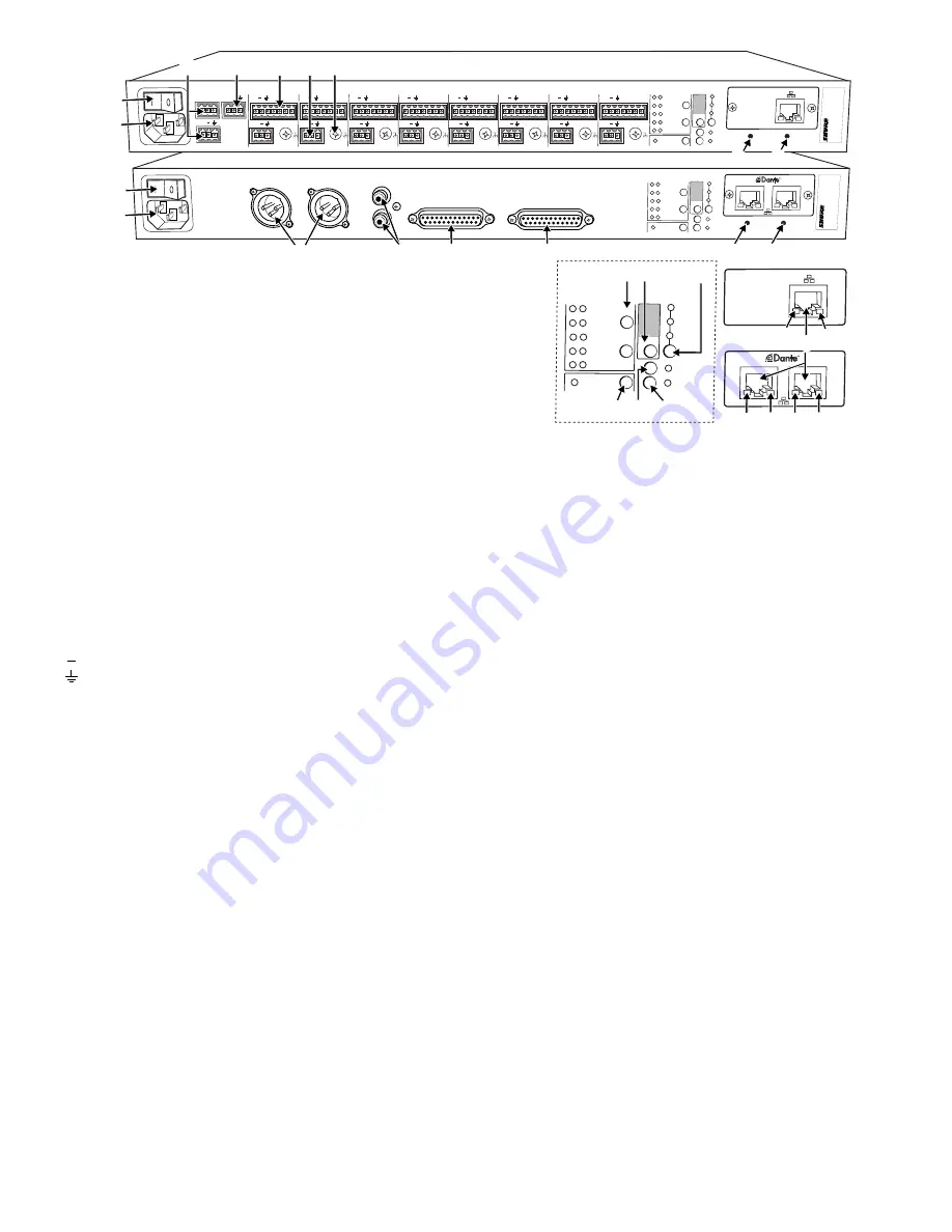
Rear Panel

① Power Switch

Turns the unit on or off. 

② AC Power Jack

Supplies AC power to the mixer when plugged into a power source. 

③ Mix A and Mix B Outputs

Active balanced outputs connect to amplifiers, DSP, mixer, or recording 

device.

④ Auxiliary Input Jack

Unbalanced aux input sums left and right channels to mono. Front and 

back panel aux inputs are summed to a mono signal and routed 

without 

automixing

 to the mix outputs.

⑤ Channel Inputs 1–8

Active-balanced microphone- or line-level inputs.

Block Connectors

+

: Audio +

: Audio −

: Audio ground

gate

: Logic gate out

mute

: Logic mute in

ovrd

: Logic override in

gnd

: Logic ground

DB25 Connector

Pins

: Audio plus, audio negative and audio ground. See Specifications 

for details.

⑥ Direct Outputs 1–8

Each channel has a dedicated, impedance-balanced direct output on 

the back panel that can be selected from one of five stages in the signal 

path. See Configuring the Inputs and Outputs for details on direct output 

routing. 

⑦ Chassis Ground Screw 1–8

Provides an optional connection for microphone shield wire to chassis 

ground.

⑧ IntelliMix Select Buttons

Scrolls through IntelliMix presets for each mix output. When 

dual mixer

 is 

off, the 

A

 button sets the mode for both Mix A and Mix B.

⑨ Dual Mixer Button

Sets the SCM820 as a dual mixer, indicated by the green LED.

⑩ Channel Select Button and Display

Press to select a single channel (1–8) or all channels (

A) when changing 

input gain or phantom power. 

• When all channels are selected (

A), Input Level and Phantom Power 

LED indicators only illuminate if all channels have the same setting. 

• 

L is displayed when the mixer is in lockout mode.

⑪ Input Gain Selection and LED Indicator

Sets the analog input gain level for the selected channel(s), illuminating 

the green LED. All LEDs are off when the channel's audio source is set to 

Network from the GUI.

⑫ Phantom Power Button and LED Indicator

Supplies 48 VDC phantom power to the selected channel(s), illuminating 

the green LED. Phantom Power is disabled in the line (+0dB) gain setting.

⑬ Auto Link Button and LED Indicator

Enables networked SCM820-DAN mixers to automatically form a link 

group. Link Groups enable a larger audio mix by incorporating inputs from 

two or more mixers. See Link Groups for more details.

⑭ Lockout Button and LED Indicator

Hold for five seconds to disable front and back panel controls. The front 

panel 

lockout

 LED illuminates red (flashing red during an adjustment 

attempt) and the back panel channel display shows 

L

.

⑮ Reset Button

Press and hold for five seconds to reboot the mixer with default system 

settings restored.

⑯ Network Ports

RJ-45 jacks for network connection.

⑰ Network Status LED (Green)

Off 

= no network link

On 

= network link established

Flashing 

= network link active

⑱ Network Speed LED (Amber)

SCM820: 

Off = 10 Mbps

On = 100 Mbps

SCM820-DAN: 

Off = 10/100 Mbps

On = 1 Gbps

Summary of Contents for SCM820 Digital IntelliMix

Page 1: ...27A20290 Rev 1 2013 Shure Incorporated SCM820 Digital IntelliMix Automatic Mixer ...

Page 2: ...he cart apparatus combination to avoid injury from tip over 13 UNPLUG this apparatus during lightning storms or when unused for long periods of time 14 REFER all servicing to qualified service personnel Servicing is required when the ap paratus has been damaged in any way such as power supply cord or plug is damaged liquid has been spilled or objects have fallen into the apparatus the apparatus ha...

Page 3: ...Mixer Operation 10 Networking 11 Network Overview 11 Digital Audio Networking 11 Dante Software by Audinate 13 Dante Controller 13 Dante Virtual Soundcard 13 Application Examples 14 Creating a Link Group 14 Integrating with Other Systems 14 Configuring for Use with a Choir 14 Internet Calling 15 Logic 15 Troubleshooting 16 Event Log 17 Front Panel Error Messages 17 Important Product Information 17...

Page 4: ...nd to achieve a natural sounding audio program even during long pauses in conversation Mixer Modes The mixer operates in one of five Mix Modes Classic Smooth Extreme Custom or Manual The first three are factory settings that offer a range of reliable automixing styles IntelliMix is configurable in Custom mode and turned off in Manual mode Classic Classic mode emulates the default settings of the c...

Page 5: ... Mix B or both for adjustment with the master knob and monitoring on the LED ring and headphone output Note When both Mix A and Mix B are selected the headphone output only monitors Mix A Mix Status Indicator LED Mix Status Green Mix is selected for adjustment and listening on the headphone output Amber Limiter is bypassed Red Mix is muted Audio Output Meters Monitor the output signal level and li...

Page 6: ...gnal path See Configuring the Inputs and Outputs for details on direct output routing Chassis Ground Screw 1 8 Provides an optional connection for microphone shield wire to chassis ground IntelliMix Select Buttons Scrolls through IntelliMix presets for each mix output When dualmixer is off the A button sets the mode for both Mix A and Mix B Dual Mixer Button Sets the SCM820 as a dual mixer indicat...

Page 7: ...i i i i i i i i i i i gain low cut hi shelf ch meter iiii i i i i i i i i i i i i i i i i gain low cut hi shelf ch meter iiii i i i i i i i i i i i i i i i i iiii i i i i i i i i i i i i i i i i 320 Hz 25 Hz 92 Hz 2 dBFS 50 dBFS 24 dBFS 60 dBFS 0 dBFS dB 18 dB dB 18 dB 0 dB 0 dB 12 dB 12 dB 0 dB MASTER gain A B limiter iiii i i i i i i i i i i i i i i i i MASTER gain A B limiter 16 dBFS gain low c...

Page 8: ... push to solo hold to mute 1 2 3 4 5 6 7 8 A B HEADPHONE IntelliMix SCM820 AUX IN MASTER lockout power ethernet network audio automix link dual mixer LIM A B 9 18 24 36 48 60 0 gain limiter L R SUM gain low cut hi shelf meter push to solo hold to mute 1 2 3 4 5 6 7 8 A B HEADPHONE IntelliMix SCM820 AUX IN MASTER lockout power ethernet network audio automix link dual mixer LIM A B 9 18 24 36 48 60 ...

Page 9: ...36 48 60 0 gain limiter L R SUM gain low cut hi shelf meter push to solo hold to mute 1 2 3 4 5 6 7 8 A B HEADPHONE AUX IN MASTER lockout power ethernet network audio automix link dual mixer LIM A B 9 18 24 36 48 60 0 gain limiter L R SUM gain low cut hi shelf meter push to solo hold to mute 1 2 3 4 5 6 7 8 A B HEADPHONE 4 5 OUT L R mix a mix b AUX IN 7 gate IN mute ovrd gnd direct out 8 gate IN m...

Page 10: ...ut the signal by 12 dB at 5 kHz with a slop of 12dB octave Direct and Mix Outputs Assign the Direct Outputs GUI Only Assign the Direct Output for each channel from the Output tab of the GUI Pre EQ After the Input Gain Post EQ After the EQ blocks Post Fader After the channel fader IntelliMix After the IntelliMix gating decision IntelliMix NOMA After IntelliMix gating and NOMA decisions Set Mix Outp...

Page 11: ...resets and can be customized to excel in any application where multiple microphones are used at once In all modes except Manual MaxBus ensures that only one channel is opened per sound source Channel Gain in Classic Mixer 1 Talker Full gain is applied as the channel opens off attenuation gain is applied to all channels 2 Talkers As additional channels open NOMA factor decreases the level of all ch...

Page 12: ...mary secondary CHANNEL INTELLIMIX 00 0E DD AA B B CC 4 5 T L R a x b AUX IN 7 gate IN mute ovrd gnd direct out 8 gate IN mute ovrd gnd direct out 6 gate IN mute ovrd gnd direct out gate IN mute ovrd gnd direct out gate IN mute ovrd gnd direct out 3 gate IN mute ovrd gnd direct out 2 gate IN mute ovrd gnd direct out 1 gate IN mute ovrd gnd direct out lockout line A A B B manual smooth classic extre...

Page 13: ... network audio automix link dual mixer LIM A B 9 18 24 36 48 60 0 gain limiter L R SUM gain low cut hi shelf meter push to solo hold to mute 1 2 3 4 5 6 7 8 A B HEADPHONE IntelliMix SCM820 AUX IN MASTER lockout power ethernet network audio automix link dual mixer LIM A B 9 18 24 36 48 60 0 gain limiter L R SUM gain low cut hi shelf meter push to solo hold to mute 1 2 3 4 5 6 7 8 A B HEADPHONE Inte...

Page 14: ...8 60 0 gain limiter L R SUM gain low cut hi shelf meter push to solo hold to mute 1 2 3 4 5 6 7 8 A B HEADPHONE IntelliMix SCM820 AUX IN MASTER lockout power ethernet network audio automix link dual mixer LIM A B 9 18 24 36 48 60 0 gain limiter L R SUM gain low cut hi shelf meter push to solo hold to mute 1 2 3 4 5 6 7 8 A B HEADPHONE IntelliMix SCM820 AUX IN MASTER lockout power ethernet network ...

Page 15: ...nte has a predetermined selection of latency settings When the same setting is selected it ensures that all Dante devices on the network are in sync The latency setting for Dante devices should be set according to the number of switches in the network The SCM820 network card has an internal switch chip and counts as a switch For example one SCM820 connected to an external switch equals two switche...

Page 16: ...ear at the mixer outputs This is the default setting for the mixer Local Only its own eight input channels appear at the mixer s Mix Outputs Aux Channel The aux channel can be set to Local or Global from GUI Inputs Tab Local Aux keeps the Aux signal from appearing on the mix output of other networked boxes Integrating with Other Systems Feedback Controller or Equalizer When setting up a sound syst...

Page 17: ...rophone activates all other microphones mute automatically Remote Channel Open Indicators Remote indicators can be used to indicate when a talker s microphone is on Connect the LEDs and a 5 volt supply to the GATE OUT pin To avoid switching clicks in the audio output do not ground the power supply negative terminal in the audio system or rack ground Important If a single cable is used for the micr...

Page 18: ... that five or less windows are open to the same GUI Disable software meters from GUI Preferences tab See Network section for properly setting up the network Network Audio and Link Groups Problem Indicator Solution Network audio is missing or distorted Network Audio LED Green Check channel and mix gain Flashing Green Ensure the mixer has a stable network connection Use Dante Controller software DC ...

Page 19: ...nected directly to a public internet network EMC conformance to Environment E2 Commercial and Light Industrial Testing is based on the use of supplied and recommended cable types The use of other than shielded screened cable types may degrade EMC performance Changes or modifications not expressly approved by Shure Incorporated could void your authority to operate this equipment This Class B digita...

Page 20: ...network audio automix link dual mixer LIM A B 9 18 24 36 48 60 0 gain limiter L R SUM gain low cut hi shelf meter push to solo hold to mute 1 2 3 4 5 6 7 8 A B HEADPHONE IntelliMix SCM820 AUX IN MASTER lockout power ethernet network audio automix link dual mixer LIM A B 9 18 24 36 48 60 0 gain limiter L R SUM gain low cut hi shelf meter push to solo hold to mute 1 2 3 4 5 6 7 8 A B HEADPHONE Intel...

Page 21: ...kout 2 Device List Displays the name of the mixer as set in the Preferences tab Click the drop down bar and select a device to open its GUI in a new window or tab 3 Identify When clicked this commands the mixer s LEDs to flash for easy identification 4 Log Off When a password is set this button logs off of the device and returns the user to the Log On page This button does not appear when there is...

Page 22: ...indicators function separately for each mix 8 Clip Indicator Illuminates when the signal is clipping the input preamp The light will stay lit as a warning for 2 seconds Select a lower Input Gain Level to avoid clipping Input 9 Input Meter Displays signal level information The meter is customizable in the Preferences tab to monitor the following options Realtime monitoring of the input signal level...

Page 23: ...s Tab 6 Routing Routes the channel to the Mix A or Mix B output The routing options depend on the Mixer Type Single Mixer Type the channel can route to both or neither mixes Dual Mixer Type the channel can route to Mix A Mix B both or neither mixes 7 Gating Logic When the mixer is set to Dual Mixer operation this setting determines whether Mix A or Mix B controls the hardware functions IntelliMix ...

Page 24: ...ntain a uniform system gain comparable to that of a single open channel Note Off Attenuation Last Mic Lock On and NOMA are disabled in this setting 18 Off Attenuation Sets the amount of attenuation applied to closed channels This is disabled when the Gain Scaling is set to Adaptive 19 Hold Time In Full gating style this determines how long a channel remains open after the signal level drops below ...

Page 25: ...Width and Q This setting adjusts the bandwidth of the EQ adjustment from very narrow 1 70 octave or 100 99Q to very wide 4 octaves or 0 27 Q Gain Sets boost or cut of the EQ setting from 18 to 18 dB 8 Lim Limiter Indicator Illuminates to indicate that the signal has exceed the limiter threshold engaging the limiter 9 Clip Indicator Illuminates when the signal has clipped the outputs holding for tw...

Page 26: ...e Auto Link enabled When a device is placed in a group it will automatically configure the unit to the group s settings 3 Stand Alone Devices List Displays all mixers that function independently of a link group 4 New Group Button Creates a new Link Group to the list 5 Delete Group Button Deletes an empty group from the Linked Device Group window This is inactive if there are any mixers in the grou...

Page 27: ...ferences Tab 9 IntelliMix Metering Changes the GUI Input meters to display IntelliMix attenuation applied in realtime as displayed with an orange meter Channels that gate open will display more gain than channels that are closed attenuated in the mix 10 Disable Software Meters When selected this turns off all metering in the GUI Disabling meters helps to reduce network traffic This does not affect...

Page 28: ...the password Once a password is set any user can log on as a Guest to view the GUI without changing settings To clear a password and allow anyone full editing rights 4 Log on to the GUI 5 Enter the current password into the Old Password text field 6 Press the Clear button 20 Load Settings Button Uploads a file of saved settings to the device This reconfigures the IntelliMix settings of all units i...

Page 29: ...the GUI 4 Language Sets the language of the GUI This setting is saved to the computer s cookies Event Log The event log provides a detailed account of mixer activity from the moment the mixer is powered on The log collects and time stamps up to 1 000 activity entries for the mixer The Event Log is a reference tool for troubleshooting when calling Shure Systems Support or Service Department The log...

Page 30: ...Level Line 0dB Aux 20dB Mic 46dB Active Balanced 350 Ω 20 dBV 0 dBV 26 dBV Direct Output Configuration Impedance Max Output Level Impedance Balanced 150 Ω 20 dBV Headphone Output 6 35 mm 1 4 TRS 100 mW 350 Ω dual mono will drive stereo phones Digital Signal Processing AD DA Converter 24 bit 48 kHz 113 dB dynamic range typical Internal Processing 32 bit Latency From channel input to mix output Esti...

Page 31: ...covery Open 427 udp SLP Required for service discovery Open 443 tcp HTTPS Closed 161 tcp SNMP SNMP Closed 162 tcp SNMP SNMP trap Closed 843 tcp Flash Required for embedded Adobe Flash GUI Open 2202 tcp Required for 3rd party control strings Open 5353 tcp mDNS Required for device discovery Open 5568 udp SDT Required for device control Open 8023 tcp Telnet Debug console interface Password 8180 tcp F...

Page 32: ...ual mixer 0dB mic 30dB mic phm 48 VDC CH 46dB reset CHANNEL INTELLIMIX C C B B A A D D E 0 0 0 auto link gate IN Aux Out mute ovrd gnd L R L 1 14 25 13 R GATE OUT LOGIC GROUND MUTE IN OR OVERRIDE IN 100K 10K 5 V 5 V To SCM820 IntelliMix Processing From SCM820 IntelliMix Processing Main Outputs Inputs Direct and Main Outputs Aux Input Aux Input 1 2 3 4 5 6 7 8 Positive Negative Ground Channel Input...

Page 33: ...mail info shure com hk United States Canada Latin America Caribbean Shure Incorporated 5800 West Touhy Avenue Niles IL 60714 4608 USA Phone 847 600 2000 Fax 847 600 1212 USA Fax 847 600 6446 Email info shure com Europe Middle East Africa Shure Europe GmbH Jakob Dieffenbacher Str 12 75031 Eppingen Germany Phone 49 7262 92490 Fax 49 7262 9249114 Email info shure de ...

Reviews: