background image


27(44) 


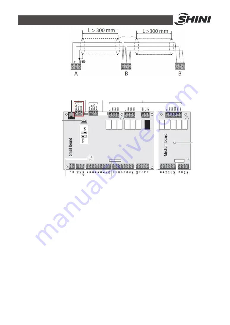
Picture 3-8: Communication Line Connection 

2)  Communication Interface   


Picture 3-9: Communication Interface Diagram 

Note: The communication cable plug-in and plug-out must be carried 
out  when  the  controller  is  powered  off.  Otherwise,  the 
communication interface would be damaged easily.   
Note: The communication cable must be connected according to the 
specification. Otherwise the communication may be abnormal.         


Summary of Contents for SICC-120A-R2

Page 1: ...SICC A R2 CFC free Refrigerant Air cooled Central Water Chiller Date Nov 2017 Version Ver B English...

Page 2: ......

Page 3: ...16 2 1 Working Principle 16 2 1 1 Working Flow Instruction 16 3 Installation and Debugging 17 3 1 Installation Notice 17 3 2 Select Installation Site 18 3 3 Bearing Platform 19 3 4 Hanging and Transp...

Page 4: ...5 4 3 5 Menu Instruction of E Unit Switch 35 4 3 6 Menu Instruction of F Maintenance 36 5 Trouble shooting 38 6 Maintenance and Repair 39 6 1 Daily Repair and Check Items 40 6 2 Monthly Periodical Che...

Page 5: ...re 3 1 Installation Space 18 Picture 3 2 Platform Installation 19 Picture 3 3 Hanging and Transporting of the Unit 20 Picture 3 4 Same Direction Way 1 22 Picture 3 5 Same Direction Way 2 22 Picture 3...

Page 6: ...6 44...

Page 7: ...prevent damage of the machine or personal injuries SICC A R2 series is applicable for cooling moulds to reduce product s molding cycle They can also be used for equipment cooling in order to maintain...

Page 8: ...nient construction l Adopts imported components like scroll compressor expansion valve which ensure stable performance The whole unit will not stop due to one module failure l When the whole unit is r...

Page 9: ...ny modifications of the machine must be approved by SHINI in order to avoid personal injury and damage to machine We shall not be liable for any damage caused by unauthorized change of the machine Our...

Page 10: ...10 44 1 3 Technical Specifications 1 3 1 SICC A R2 Series Outline Dimensions SICC 60A R2 SICC 90A R2...

Page 11: ...11 44 SICC 120A R2 Picture 1 1 Outline Dimensions 1 3 2 Flange Picture 1 2 Flange Outline Dimensions...

Page 12: ...aporator Cooling flow Flow m3 h 10 3 15 5 20 6 Pressure loss kPa 27 39 2 49 Pipe Coupler inch 5 5 5 Condenser Type Fin Style Air cooled Condenser Blower power kW 1 68 2 2 3 36 Air quantity m3 h 26 000...

Page 13: ...ner is designed for adults Keep children away from it 9 Any deeds trying to change its specification are dangerous 10 Don t use evaporable solvents oil or toluene to avoid accidents 11 Ensure this mac...

Page 14: ...careful This symbol should take more careful hereby Attention No need for regular inspection because all the electrical parts in the control unit are fixed tightly 1 4 3 Signs and Labels This is for i...

Page 15: ...man made installations operation and maintenances upon machines without referring to the Manual prior to machine using 2 Any incidents beyond human reasonable controls which include man made vicious...

Page 16: ...after a pressure downfall it comes into shell tube evaporator The low temp low pressure and saturated refrigerant absorbs the heat from cooling water to low down its temp The shell tube evaporator s r...

Page 17: ...s wire 4 The end of the electricity wire should be safe and firm 5 There phase electricity and five wires are utilized Connect the power to live wire N to zero wire and G to ground wire 6 Electric po...

Page 18: ...ct imposed by high temperature vapor or oil stain 3 Avoid being spattered by water vapor when choosing installation site near cooling water tower so to avoid any short ciruit or creepage 4 Proper vent...

Page 19: ...peration and prevent the vibration and noise transmission from interfering the under floors the absorber should be laid between the unit base and base platform Please maintain horizontal when install...

Page 20: ...d then combine them finally 2 If the large scale machine cannot be decomposed then dig hole in the wall or earth to transport it Path adjustment Adjust with the wall floor to facilitate transporting O...

Page 21: ...ank should be placed higher by at least 1m than top of the whole set of water distribution pipelines to buffer the water volume s expansion or contraction and the isolated backup water pressure to wat...

Page 22: ...e gauge 6 Thermometer 7 Flowmeter 8 Solenoid valve 9 Rubber soft pipe Picture 3 4 Same Direction Way 1 Names of Parts 1 Stop valve 2 One Way valve 3 Y type Filtration valve 4 Pump 5 Pressure gause 6 T...

Page 23: ...3 7 Essentials for Electric Wiring 1 The electricity supply should use special branch circuit 2 Wiring work should be conducted according to relevant national electric standards and grounding 3 Refer...

Page 24: ...t circuit and helps to separately control the start stop of every compressor every incoming cable needs to equip proper amount of non fuse breaker Showed in the following photo 8 Inorder to ensure per...

Page 25: ...ntroller of slave machine requires the slave machine to connect with the 220V power cable which can t use the shielded cable The common two core cable is available to connect between the slave machine...

Page 26: ...eeds to use Water Chillers of displayer control it must ensure the displayer address is set as 32 3 8 4 Communication Connection 1 Specificaiton of Communication Connection If the control cable needs...

Page 27: ...erface Diagram Note The communication cable plug in and plug out must be carried out when the controller is powered off Otherwise the communication interface would be damaged easily Note The communica...

Page 28: ...ue on the displayer Enter Enter the selected sub menu or confirm the set value 4 2 Interface Operation 4 2 1 Initial Interface Initial interface first appears after the controller is electrified for 4...

Page 29: ...od of on 3 There is no severe alarm 4 The unit has been activated by keyboard 5 The main machine unit has been activated this function only works in the subordinate machine Note If any of the above co...

Page 30: ...ubordinate machines will be forced to start And when the main machine is in off state all subordinate machines will be turned off 2 Startup and shutdown of subordinate machine provided that the unit h...

Page 31: ...ay Thus on Monday the unit is on in the periods of 8 00 12 00 and 14 00 17 00 and is off in the rest of time On Tuesday the unit is on in 8 00 17 00 and off in the rest of time Besides the unit is alw...

Page 32: ...eration 4 2 5 Password Input and Change Enter the interface of password input and the cursor blinks after is pressed At that time keys of and can be pressed to change the value When you are sure the d...

Page 33: ...be pressed to page up and down in this submenu Interface Index Description of Displayer Default Unit Description of Function A01 Current set point 12 Display the target temp of control and select the...

Page 34: ...of Function B01 Clock Alter the current time B02 Input the password of clock 0 Enter after inputting the correct password Factory default password 0000 B03 Turn on and turn off the unit at fixed time...

Page 35: ...be shared by controller so one displayer can be shared by 16 controllers That is to say datum of 16 controllers can be viewed in one displayer When the controller has access to the Internet unit switc...

Page 36: ...erface Fb System Information Fb01 Version Display the version of current program and hardware Fc Summer Winter Fc01 State Summer Press Enter to switch between summer and winter Fd Operation Time Fd01...

Page 37: ...the model is chosen through the input signal of digital value 2 Keyboard switch choose either refrigeration or heating by the menu maintenance parameter which is presented in the interface FC01 in det...

Page 38: ...Check and reset 4 Edit the value for heat flow 5 Check and reset Compressor stops immediately after it starts 1 Air inlet or outlet gets hindered 2 Condenser is dirty 3 Bad ventilation due to bad lan...

Page 39: ...pply unless emergncyoccurs 2 When failure occurs and machine stops press the main power switch alarm light will go out Check the failure and do not start the machine before trouble shooting 3 Check th...

Page 40: ...tems 1 Check if the screws loosen 2 Clean indoor air conditioner box or filter of cool air blower 3 Check if the joint of the pipelines leaks 4 Check the wire to see if there is any damage the connect...

Page 41: ...es Check all wires of the machine Check whether pressure gauges are accurate Check whether compressor temperature is normal Check whether cooling water circulation is normal 6 4 4 Weekly Check Check i...

Page 42: ...ly Check and clean filter and expansion valve Check the whole machine condition Clean condenser 6 4 8 Yearly Checking Check whether the contactor is normal 6 4 9 3 year Checking PC board replacement N...

Page 43: ...43 44 Attachment Electrical Diagram...

Page 44: ...44 44...

Reviews: