


7
.
Serial Communications Connection Procedure
13
7.2. SHIMADZU Balance Setup
Set up the SHIMADZU Balance.
7.2.1. Parameter Settings
Set parameters for the Balance.
The parameter settings vary depending on the model used.
Use one of the following parameter setting procedures appropriate for your Balance's model.
Model
Procedure to be followed
ATX-R/ATY-R series
1) Parameter settings for ATX-R/ATY-R series
UPX/UPY/UW/UX series
2) Parameter settings for UPX/UPY/UW/UX series
1) Parameter settings for ATX-R/ATY-R series
Set parameters for ATX-R/ATY-R series.
Precautions for Correct Use
Make sure the power supply is OFF before setting up.
If it is ON, the settings described in the following steps and subsequent procedures may not
be applicable.
1
Make sure AC Adapter is
powered OFF.
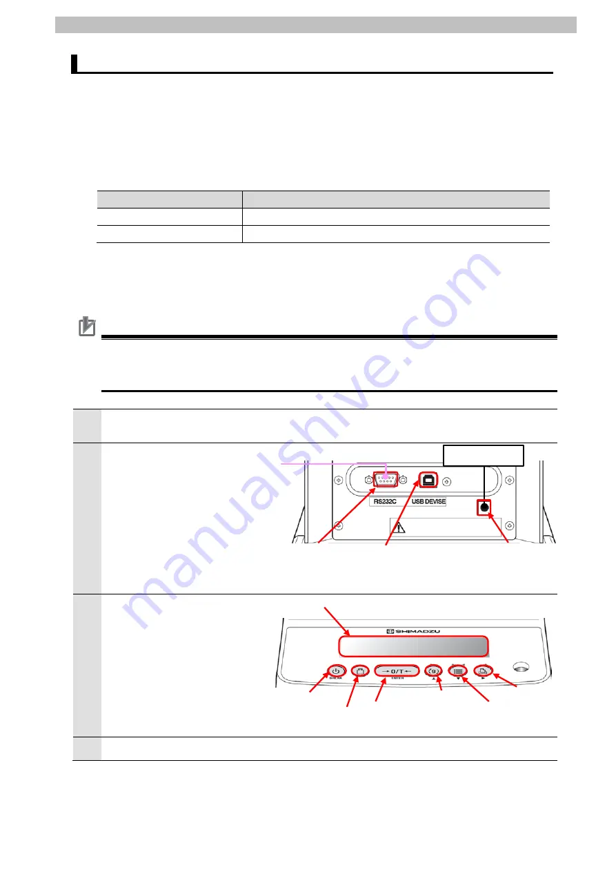
2
Check the position of the
connectors on Balance.
Connect a Serial cable
(RS-232C) to RS-232C
connector.
Connect AC Adapter to DC IN
connector.
Back view of Balance
3
Check the position of the
operation keys by referring to
the figure on the right.
Front view of Balance
4
Turn ON AC Adapter.
Serial cable (RS-232C)
AC adapter
RS-232C connector
O/T key
USB connector
CAL key
DC IN connector
MENU key
PRINT key
UNIT key
Display
panel
BREAK key
Summary of Contents for OMRON CJ Series
Page 82: ...2020 0120 0120 P732 E1 01...


