Shield T3 60 – 500KVA User Manual
49
5
220.6
220.3
220.9
50.00
50.01
50.00
1.5
2.1
2.0
0.42
0.32
0.46
33.0.051
33.0.053
0
50
100
180
260
300
0
50
100
180
260
300
0
50
100
180
300
260
5
0.0
0.0
0.0
0.0
0.0
0.0
0.0
0.0
0.0
221.0
222.5
222.5
33.0.051
33.0.053
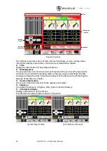
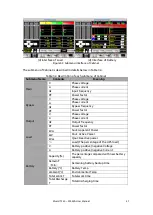
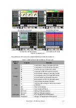
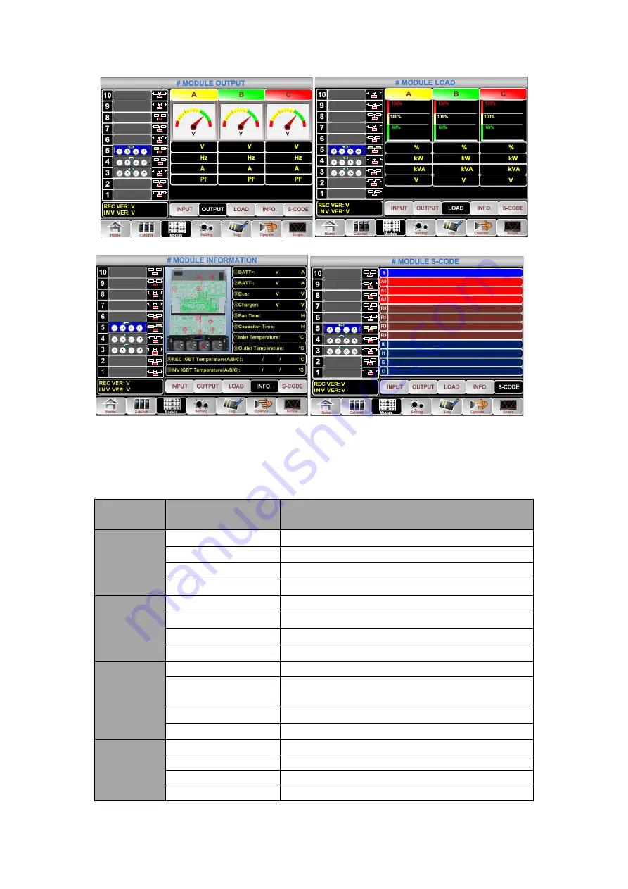
(a) Interface of Output (b) Interface of Load
33.0.051
33.0.053
0.0
0.0
0.0
0.0
400.4
398.9
0.0
0.0
0
0
21.0
23.3
22.5
20.0
20.0
25.0
20.0
25.0
5
33.0.051
33.0.053
5
1221 -0001 -0000 -0120 0000 -0000 -1102 -1000
0000 -0000 -0000 -0000 0000 -0000 -0000 -0000
0000 -0000 -0000 -0000 0000 -0000 -0000 -0000
0000 -0000 -0000 -0000 0000 -0000 -0000 -0000
1221 -0001 -0000 -0120 1000 -1101 -1111 -1111
0000 -0000 -0000 -0000 0000 -0000 -0000 -0000
0000 -0000 -0000 -0000 0000 -0000 -0000 -0000
0000 -0000 -0000 -0000 0000 -0000 -0000 -0000
1111 -1111 -1111 -1111 1111 -1011 -1111 -1111
0000 -0000 -0000 -0000 0000 -0000 -0000 -0000
0000 -0000 -0000 -0000 0000 -0000 -0000 -1000
0000 -0000 -0000 -1000 0000 -0011 -1100 -0100
(c) Interface of Information (d) Interface of S-Code
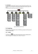
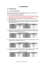
Figure3-7
Module menu
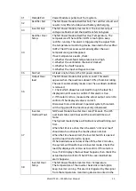
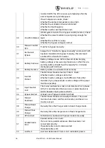
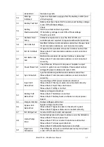
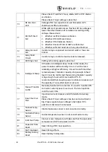
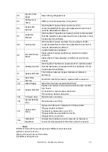
The submenus of Power unit are described below in details in
Table 3-5
Description of each submenu of
Power unit
Submenu
Name
Contents
Meaning
Input
V
Input phase voltage of selected module
A
Input phase current of selected module
Hz
Input frequency of selected module
PF
Input power factor of selected module
Output
V
Output phase voltage of selected module
A
Output phase current of selected module
Hz
Output frequency of selected module
PF
Output power factor of selected module
Load
V
Load voltage of selected module
%
Load (The percentage of the power module
selected)
KW
Pout: Active Power
KVA
Sout: Apparent Power
Information
BATT+(V)
Battery Voltage (positive)
BATT-(V)
Battery Voltage (negative)
BUS(V)
Bus Voltage(Positive &Negative)
Charger(V)
Charger Voltage(Positive &Negative)

