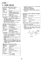
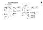
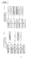

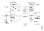
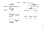
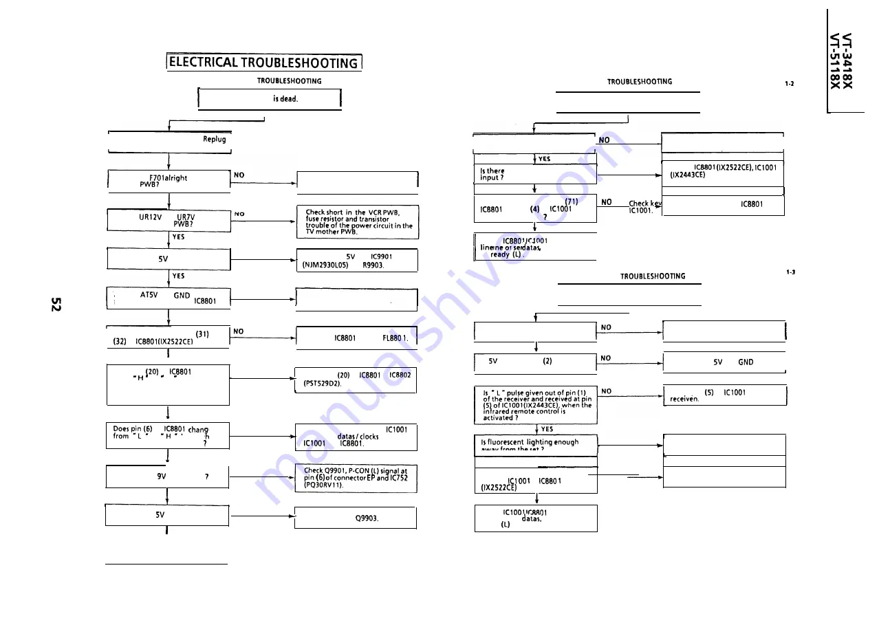
KEY-IN
VCR POWER
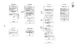
FLOW CHART NO. l-l
FLOW CHART NO.
The VCR
I
Key-h Input is not received.
I
I
Unplug the AC power cord.
it a few minutes later.
I
I
Is the key switch in good contact 7
Check the switch contact.
I
short-circuit in the key
NO
Check
and switches for poor
soldering.
I
S
the fuse
in the TV
mother
Replace the fuse
YES
I
I
YES
I
I
I
I
1
Are signals received at pin
of
and pin
of
when
l i n e s t o i n p u t
o r
the key is activated
YES
Are the
and
lines
normal in the VCR
Is the AT
line normal ?
NO
Check the AT
line,
and
Are the
and
lines
NO
properly connected with
?
Check poor soldering.
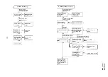
Check
and signal
of serial
serial clock and
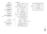
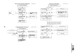
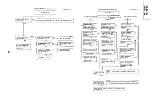
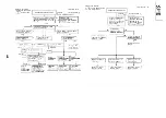
INFRARED R/C
FLOW CHART NO.
I
No operation is possible from the
infrared remote control.
I
YES
I
I
I
1
Does the infrared remote control
function ?
control as required.
Replace the infrared remote
I
Is there oscillation at pins
and
of
?
Replace
and /or
YES
I
YES
I
I
I
Is
applied at pin
of the
remote control receiver ?
Check the
and
lines.
I
t
Does pin
of
change
from to L level when
N O
Check pin
of
or
the AC cord is plugged in or ALL
CLEAR button is pressed and
released?
I
I
I
YES
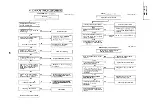
,
Check pin
of
and /or
YES
1
of
e
NO
to
level w
Check power key input to
en
the power button is pressed
and serial
between
.
and
YES
NO
away from the set ?
Reposition the set not to be
exposed to strong light.
YES
Is there short-circuit in the key
input or
or
?
YES
NO
Check key input terminals.
-
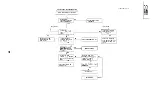
N
O
I
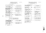
S
the PC
line normal
YES
in
of connector an
I
S
the PC
line normal ?
YES
NO
Check
Check
and signal
line of serial
serial clock and
ready
.
I
Check wire harness to mechanism.
I
Summary of Contents for VT-3418X
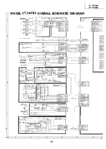
Page 54: ...VT 341 8X VT 51 18X is z 0 Y Y c U T J 2 c 4 54 ...
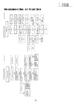
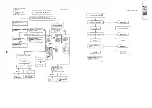
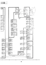
Page 61: ...VT 341 8X VT 51 18X TROUBLESHOOTING OF TV SECTION I I I I 1 I I I I I I I ___ I iiE I b z 61 ...
Page 74: ...m 3418X i T 5118X VCJ AV UNIT 7 I 8 I 9 I 10 I 11 I 12 I 74 ...
Page 76: ...VT 341 8X VT 5118X VCJ AV UNIT I 7 I 8 I 9 I 10 I 11 I 12 1 76 ...
Page 78: ...PWB B V I D E O CHROMA J U N G L E 7 I 8 I 9 I 10 I 11 I 12 I 78 ...
Page 80: ...PWE 8 I 1 V I D E O CHROMA JUNGLE hr r I 7 I 8 I 9 I 10 I 11 I 12 I 80 ...
Page 86: ...VT 341 8X VT 5118X 7 I 8 I 9 I 10 I 11 I 12 I 86 ...
Page 88: ...rr J I I TUNER w2o1 m ...
Page 89: ...n 3 30 ...
Page 90: ...VT 341 8X VT 5118X VCJ AV UNIT DUNTK830 I WEV3 I I I m c I 7 I 8 I 9 I 10 1 11 I 12 I 90 ...
Page 92: ... VT 341 8X VT 51 18X DUNTK8302WEV 1 DUNTK8303WEV I I 7 I 8 I 9 I 10 I 11 I 12 I 92 ...
Page 94: ...VT 341 8X VT 5118X DUNTK8302WEV3 DUNTK8303WEV3 7 I 8 I 9 I 10 I 11 I 12 I 94 ...
Page 97: ... _ _ _ __ D I m I n I t3 I m I n I GI I I 1 ...
Page 98: ...Memo _ a _ _ 98 ...
Page 102: ...I REC I w r I I I CAPSTAN FG 7 I 8 I 9 I 10 I 11 I 12 1 102 ...
Page 106: ...CASSETTE SW REC TIP I ED M I I II DFfwPG I I I I I I I I I I I I ...
Page 110: ...VT 341 8X I VT 5118X 1 J 7 I 8 I 9 I 10 I 11 I 12 I 110 ...
Page 112: ...VT 341 8X I T 5118X 1 WAVEFORMS 112 ...
Page 115: ...SCHEMATIC DIAGRAM n VCR Main Unit r 7 I 1 I 2 I 3 I 4 I 5 I 6 115 ...
Page 119: ...D I c9 I n I u I m I n I GI I I I ...
Page 123: ...D I a I n I u I m I n I GI I I I ...
Page 124: ...11 I 12 I ...
Page 126: ...J l J I i _ _ _ ___ I _ _ n f f 7 I 8 I 9 I 10 I 11 I 12 126 ...
Page 152: ...VT 341 8X VT 5118X MECHANISM CHASSIS PARTS 152 ...
Page 155: ...H G F E D C B A CASSETTE HOUSING CONTROL PARTS 1 I 2 I 3 I 4 I 5 I 6 I 155 ...
Page 157: ...MECt 1 I 2 I 3 I 4 I 5 I 6 157 ...
Page 158: ...VT 341 8X VT 51 18X I I 7 I 8 I 9 I 10 I 11 I 12 I 158 ...
Page 161: ...H G F E D C B A VT 341 8X VT 5118X 1 2 I 3 I 4 I 5 I 6 161 ...
Page 162: ...VT 341 8X VT 51 18X I I 7 I 8 I 9 I 10 I 11 I 162 12 I ...
Page 163: ... 1 DEL VT 3418X CABINET AND MECHANICAL PARTS 0 II I L e e m I w F J 1 I 2 I 3 I 4 I 5 I 6 163 ...
Page 164: ... ...
Page 169: ...Memo m 169 ...
Page 170: ...S H A R P T98 19 S Printed in Japan 0 w s MW KD ...