


n
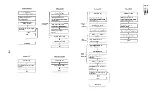
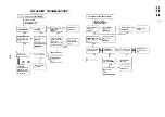
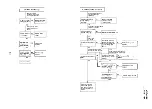
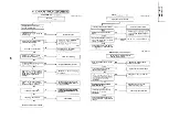
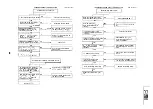
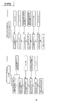
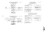
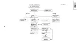
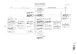
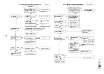
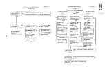
MECHANISM OPERATION FLOWCHART
CASSETTE INSERTION STOP
0
l
This flowchart describes the outline of the mechanism’s operation, but does not give its details.
l
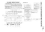
Function of cam switch bit reading.
The on/off of cam switch is cam position switch
input signals in conditions as shown in below.
End
I
J
I
1
Insert cassette.
I
I Cassette is ejected and loading
I
SW
SW
SW
‘ON’
‘ON’
‘ON’
‘ON’
‘ON‘
‘ON’
‘OFF’
Mechanism position SW
input
L
H
H
H
H
L
H
I
t
,
motor stops.
I
Turn off cassette switch.
I
t
Cassette switch turns on.
I
1
I
Mechanism
input H L H H L I
Mechanism position
input H L I L I H
I I
I
Loading motor starts in normal
direction and master cam clockwise.
Loading motor turns in reverse
direction and master cam
t
counterclockwise.
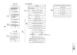
Does cassette control clutch come
off within
sec. after cassette
t
switch has turned off?
(Cassette is judged caught halfway.)
Mechanism position SW
input
H
H
H
L
L
H
Cassette
inserting
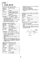
Are start/end sensors at low level
before cassette insertion?
NO
(Cassette LED or some
judged defective.)
input
input
input
Input
Mechanism position SW
Mechanism position SW
Mechanism position SW
Mechanism position SW
SW
part is
I
Drum motor starts.
I
t
Pinch roller comes into contact.
Mechanism
position SW
h
Cam switch is at
position.
position SW
Mechanism
position
.
:
:
: :
. .
. ,
: : :
: : :
: :
:
. : :
. .
: :
. .
. .
. .
: :
:
:
:
:
:
. .
: :
:
: :
. ,
: .
: :
: :
: :
:
. Shift zone
: :
.
: .
:
: :
: :
. .
Is drum
pulse outputted?
Unloading
I
End
CAM SW
SW
CD SW
SW
SW
Summary of Contents for VT-3418X
Page 54: ...VT 341 8X VT 51 18X is z 0 Y Y c U T J 2 c 4 54 ...
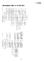
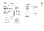
Page 61: ...VT 341 8X VT 51 18X TROUBLESHOOTING OF TV SECTION I I I I 1 I I I I I I I ___ I iiE I b z 61 ...
Page 74: ...m 3418X i T 5118X VCJ AV UNIT 7 I 8 I 9 I 10 I 11 I 12 I 74 ...
Page 76: ...VT 341 8X VT 5118X VCJ AV UNIT I 7 I 8 I 9 I 10 I 11 I 12 1 76 ...
Page 78: ...PWB B V I D E O CHROMA J U N G L E 7 I 8 I 9 I 10 I 11 I 12 I 78 ...
Page 80: ...PWE 8 I 1 V I D E O CHROMA JUNGLE hr r I 7 I 8 I 9 I 10 I 11 I 12 I 80 ...
Page 86: ...VT 341 8X VT 5118X 7 I 8 I 9 I 10 I 11 I 12 I 86 ...
Page 88: ...rr J I I TUNER w2o1 m ...
Page 89: ...n 3 30 ...
Page 90: ...VT 341 8X VT 5118X VCJ AV UNIT DUNTK830 I WEV3 I I I m c I 7 I 8 I 9 I 10 1 11 I 12 I 90 ...
Page 92: ... VT 341 8X VT 51 18X DUNTK8302WEV 1 DUNTK8303WEV I I 7 I 8 I 9 I 10 I 11 I 12 I 92 ...
Page 94: ...VT 341 8X VT 5118X DUNTK8302WEV3 DUNTK8303WEV3 7 I 8 I 9 I 10 I 11 I 12 I 94 ...
Page 97: ... _ _ _ __ D I m I n I t3 I m I n I GI I I 1 ...
Page 98: ...Memo _ a _ _ 98 ...
Page 102: ...I REC I w r I I I CAPSTAN FG 7 I 8 I 9 I 10 I 11 I 12 1 102 ...
Page 106: ...CASSETTE SW REC TIP I ED M I I II DFfwPG I I I I I I I I I I I I ...
Page 110: ...VT 341 8X I VT 5118X 1 J 7 I 8 I 9 I 10 I 11 I 12 I 110 ...
Page 112: ...VT 341 8X I T 5118X 1 WAVEFORMS 112 ...
Page 115: ...SCHEMATIC DIAGRAM n VCR Main Unit r 7 I 1 I 2 I 3 I 4 I 5 I 6 115 ...
Page 119: ...D I c9 I n I u I m I n I GI I I I ...
Page 123: ...D I a I n I u I m I n I GI I I I ...
Page 124: ...11 I 12 I ...
Page 126: ...J l J I i _ _ _ ___ I _ _ n f f 7 I 8 I 9 I 10 I 11 I 12 126 ...
Page 152: ...VT 341 8X VT 5118X MECHANISM CHASSIS PARTS 152 ...
Page 155: ...H G F E D C B A CASSETTE HOUSING CONTROL PARTS 1 I 2 I 3 I 4 I 5 I 6 I 155 ...
Page 157: ...MECt 1 I 2 I 3 I 4 I 5 I 6 157 ...
Page 158: ...VT 341 8X VT 51 18X I I 7 I 8 I 9 I 10 I 11 I 12 I 158 ...
Page 161: ...H G F E D C B A VT 341 8X VT 5118X 1 2 I 3 I 4 I 5 I 6 161 ...
Page 162: ...VT 341 8X VT 51 18X I I 7 I 8 I 9 I 10 I 11 I 162 12 I ...
Page 163: ... 1 DEL VT 3418X CABINET AND MECHANICAL PARTS 0 II I L e e m I w F J 1 I 2 I 3 I 4 I 5 I 6 163 ...
Page 164: ... ...
Page 169: ...Memo m 169 ...
Page 170: ...S H A R P T98 19 S Printed in Japan 0 w s MW KD ...