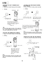
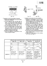

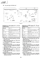
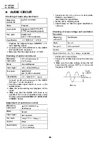
Push the
or
tracking button to check
that a flat response is obtained on the
envelope waveform.
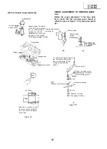
Secure the guide roller by tightening the
guide roller setscrew in the unloading mode.
Play back the tape drive train alignment tape
to check that the envelope waveform does
not change.
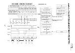
Adjust the playback switching point.
Check the flatness of the envelope waveform
and sound by playing back a recorded tape.
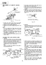
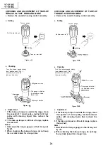
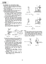
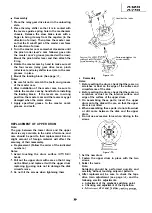
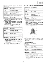
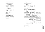
Adjustment of A/C head X-position.
a) Push the (
and
tracking buttons at the
same time to the preset mode.
Rotate the X-position adjusting nut with an
adjusting box driver, and adjust the
head
position for maximum head
switching pulse
low side envelope.
X-position adjusting nut
mm
Main chassis
Figure
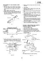
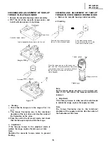
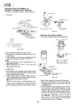
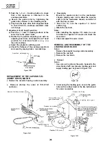
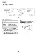
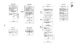
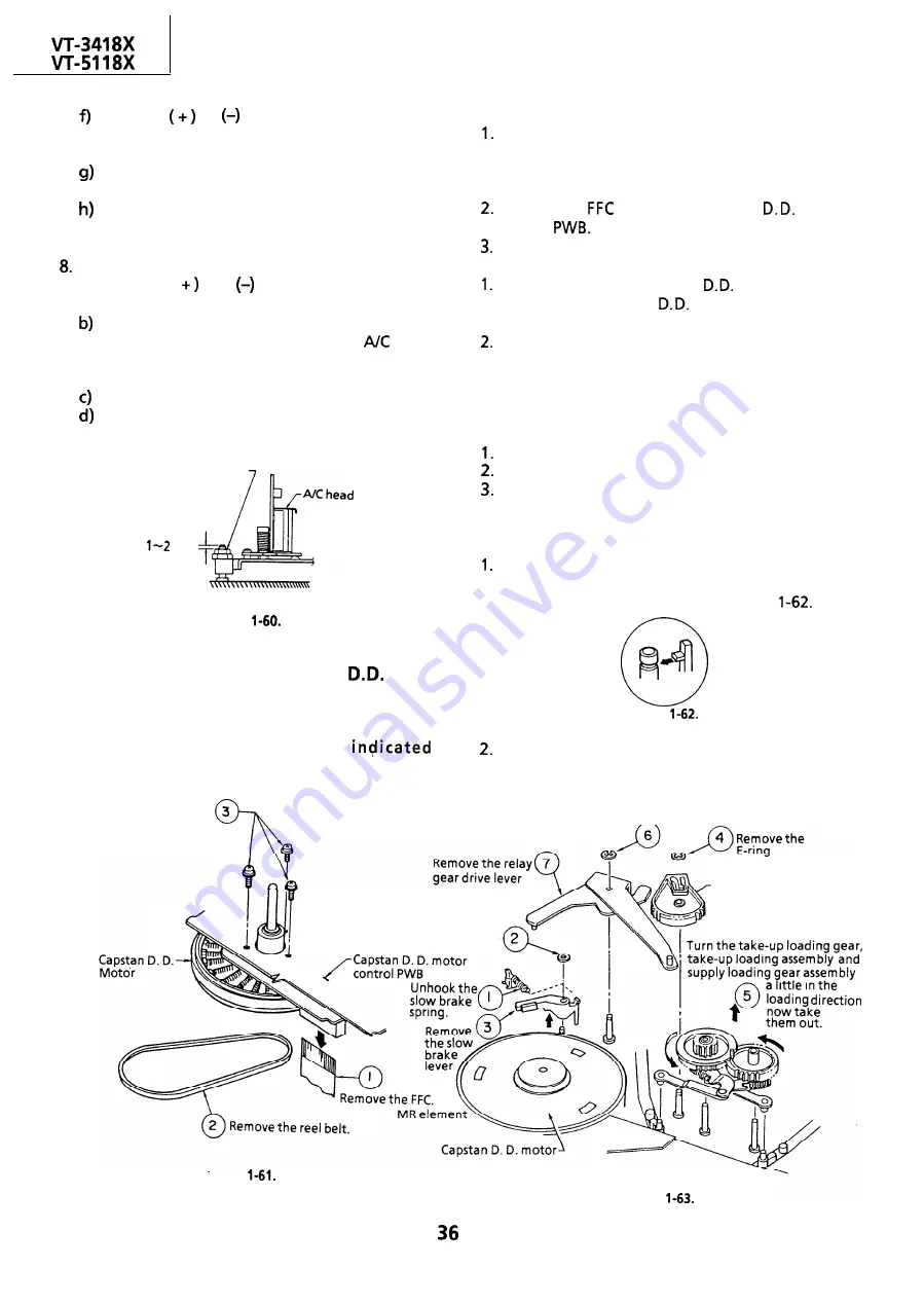
REPLACEMENT OF THE CAPSTAN
(DIRECT DRIVE) MOTOR
l
Remove the cassette housing control assembly.
l
Removal (Follow the order of
numbers.)
Remove the three screws.
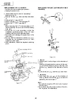
l
Reassembly
Mount the capstan motor on the mechanism
chassis making sure not to allow the capstan
shaft to hit the mechanism chassis, and attach it
with the three screws.
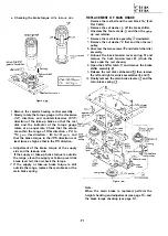
Insert the
into the capstan
motor
control
Attach the reel belt.
Notes:
After installing the capstan
motor, be sure
to rotate the capstan
motor and check the
movement.
Check and adjust the servo circuit.
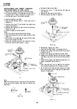
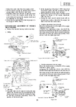
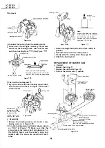
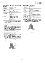
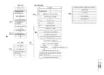
REMOVAL AND REASSEMBLY OF THE
LOADING GEAR BLOCK
Remove the cassette housing control assembly.
Remove the reel belt.
Remove the reel block.
Notes:
l
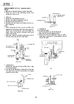
Removal
Notes:
Use care not to deform the parts hooked to the
slow brake shaft cap, take-up loading gear and
supply loading gear as shown in Figure
Figure
in removing the loading gear, secure the guide
roller with a rubber band or the like beforehand
for easier reassembly.
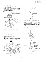
Remove the E-ring
Loading relay gear
Remove the washer
Figure
Figure
Summary of Contents for VT-3418X
Page 54: ...VT 341 8X VT 51 18X is z 0 Y Y c U T J 2 c 4 54 ...
Page 61: ...VT 341 8X VT 51 18X TROUBLESHOOTING OF TV SECTION I I I I 1 I I I I I I I ___ I iiE I b z 61 ...
Page 74: ...m 3418X i T 5118X VCJ AV UNIT 7 I 8 I 9 I 10 I 11 I 12 I 74 ...
Page 76: ...VT 341 8X VT 5118X VCJ AV UNIT I 7 I 8 I 9 I 10 I 11 I 12 1 76 ...
Page 78: ...PWB B V I D E O CHROMA J U N G L E 7 I 8 I 9 I 10 I 11 I 12 I 78 ...
Page 80: ...PWE 8 I 1 V I D E O CHROMA JUNGLE hr r I 7 I 8 I 9 I 10 I 11 I 12 I 80 ...
Page 86: ...VT 341 8X VT 5118X 7 I 8 I 9 I 10 I 11 I 12 I 86 ...
Page 88: ...rr J I I TUNER w2o1 m ...
Page 89: ...n 3 30 ...
Page 90: ...VT 341 8X VT 5118X VCJ AV UNIT DUNTK830 I WEV3 I I I m c I 7 I 8 I 9 I 10 1 11 I 12 I 90 ...
Page 92: ... VT 341 8X VT 51 18X DUNTK8302WEV 1 DUNTK8303WEV I I 7 I 8 I 9 I 10 I 11 I 12 I 92 ...
Page 94: ...VT 341 8X VT 5118X DUNTK8302WEV3 DUNTK8303WEV3 7 I 8 I 9 I 10 I 11 I 12 I 94 ...
Page 97: ... _ _ _ __ D I m I n I t3 I m I n I GI I I 1 ...
Page 98: ...Memo _ a _ _ 98 ...
Page 102: ...I REC I w r I I I CAPSTAN FG 7 I 8 I 9 I 10 I 11 I 12 1 102 ...
Page 106: ...CASSETTE SW REC TIP I ED M I I II DFfwPG I I I I I I I I I I I I ...
Page 110: ...VT 341 8X I VT 5118X 1 J 7 I 8 I 9 I 10 I 11 I 12 I 110 ...
Page 112: ...VT 341 8X I T 5118X 1 WAVEFORMS 112 ...
Page 115: ...SCHEMATIC DIAGRAM n VCR Main Unit r 7 I 1 I 2 I 3 I 4 I 5 I 6 115 ...
Page 119: ...D I c9 I n I u I m I n I GI I I I ...
Page 123: ...D I a I n I u I m I n I GI I I I ...
Page 124: ...11 I 12 I ...
Page 126: ...J l J I i _ _ _ ___ I _ _ n f f 7 I 8 I 9 I 10 I 11 I 12 126 ...
Page 152: ...VT 341 8X VT 5118X MECHANISM CHASSIS PARTS 152 ...
Page 155: ...H G F E D C B A CASSETTE HOUSING CONTROL PARTS 1 I 2 I 3 I 4 I 5 I 6 I 155 ...
Page 157: ...MECt 1 I 2 I 3 I 4 I 5 I 6 157 ...
Page 158: ...VT 341 8X VT 51 18X I I 7 I 8 I 9 I 10 I 11 I 12 I 158 ...
Page 161: ...H G F E D C B A VT 341 8X VT 5118X 1 2 I 3 I 4 I 5 I 6 161 ...
Page 162: ...VT 341 8X VT 51 18X I I 7 I 8 I 9 I 10 I 11 I 162 12 I ...
Page 163: ... 1 DEL VT 3418X CABINET AND MECHANICAL PARTS 0 II I L e e m I w F J 1 I 2 I 3 I 4 I 5 I 6 163 ...
Page 164: ... ...
Page 169: ...Memo m 169 ...
Page 170: ...S H A R P T98 19 S Printed in Japan 0 w s MW KD ...