
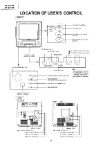


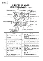
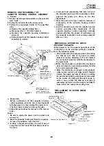
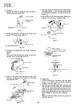
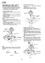
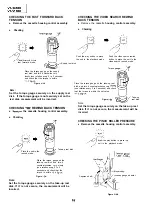
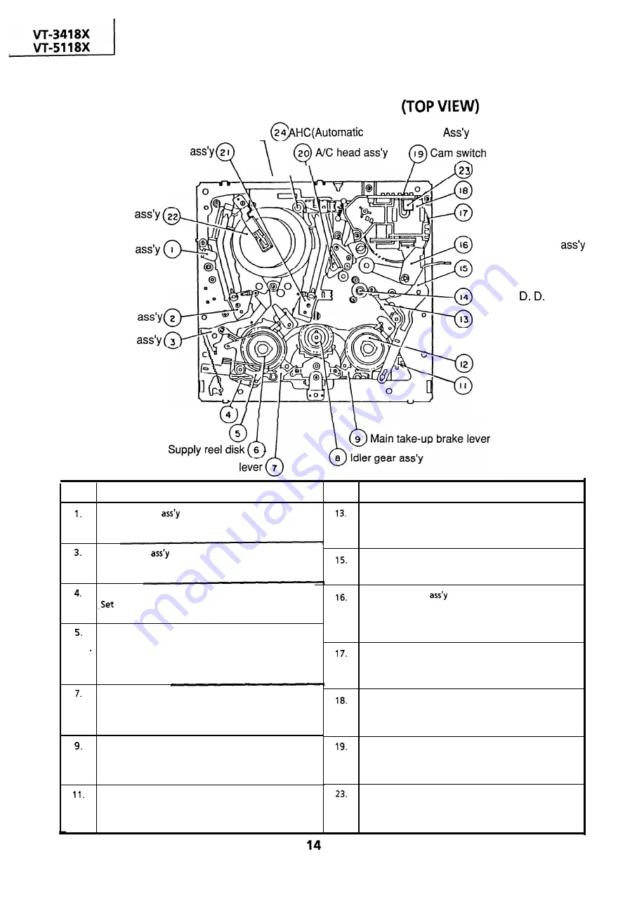
Take-up pole
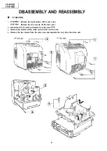
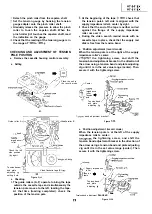
FUNCTION OF MAJOR
MECHANICAL PARTS
Head Cleaner)
Drum
Full erase head
Supply pole base
Tension arm
base
I
Dew sensor
Brake shifter
Loading motor
Master cam
Pinch roller lever
Relay shifter lever
Capstan motor
Reverse guide
Take-up reel disk
Video
lever
search brake
Back tension lever
Main supply brake
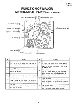
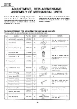
No.
Function
No.
Function
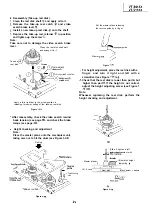
Full erase head
Erase the whole records on the tape in the recording
mode.
Tension arm
Detects the tension of tape while running, and brakes
the supply reel disk via the tension band.
Reverse guide
Pulls
out the tape in the video search rewind mode,
and controls the tape drive train height with the upper
and lower guides.
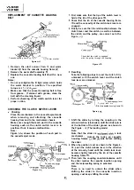
Relay shifter lever
Transmits the operation of the master cam to the
brake shifter, and operates the reverse guide.
Brake shifter
the position of brake or the like in accordance with
Pinch roller lever
Press-fits the tape to the capstan during tape running.
the modes such as stop and playback.
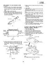
The right protrusion switches the clutch of the cassette
housing control assembly in “tape eject”, and makes
Back tension lever
the mechanism eject the tape.
Brakes the supply reel disk to a certain degree to .
p r e v e n t t a p e s l a c k e n i n g d u r i n g “ h a l f - l o a d i n g ” ,
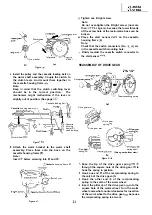
Master cam
“loading” and “shifting from playback to video search
Turns clockwise during loading, and counterclockwise
rewind”.
during unloading, and moves the shifter or the like in
accordance with each mode.
Main supply brake lever
Brakes the supply reel disk to prevent tape slackening
Loading motor
when the unit is stopped in fast forward or rewind
A motive power which drives the mechanism. It
transmits the power to the master cam and cassette
mode.
housing control assembly via the belt.
Main take-up brake lever
Cam switch
Brakes the take-up reel disk to prevent tape slackening
Rotates synchronously with the master cam, and
when the unit is stopped in fast forward or rewind
detects the position of each mode by means of the
mode.
internal switch.
Video search brake lever
Dew sensor
It is in contact with the take-up reel disk normally, and
An element which detects condensation inside the
brakes it to a certain degree. It applies larger brake in
unit. This element is activated, when it senses
the video search rewind mode.
condensation, to interrupt the mechanism.
Summary of Contents for VT-3418X
Page 54: ...VT 341 8X VT 51 18X is z 0 Y Y c U T J 2 c 4 54 ...
Page 61: ...VT 341 8X VT 51 18X TROUBLESHOOTING OF TV SECTION I I I I 1 I I I I I I I ___ I iiE I b z 61 ...
Page 74: ...m 3418X i T 5118X VCJ AV UNIT 7 I 8 I 9 I 10 I 11 I 12 I 74 ...
Page 76: ...VT 341 8X VT 5118X VCJ AV UNIT I 7 I 8 I 9 I 10 I 11 I 12 1 76 ...
Page 78: ...PWB B V I D E O CHROMA J U N G L E 7 I 8 I 9 I 10 I 11 I 12 I 78 ...
Page 80: ...PWE 8 I 1 V I D E O CHROMA JUNGLE hr r I 7 I 8 I 9 I 10 I 11 I 12 I 80 ...
Page 86: ...VT 341 8X VT 5118X 7 I 8 I 9 I 10 I 11 I 12 I 86 ...
Page 88: ...rr J I I TUNER w2o1 m ...
Page 89: ...n 3 30 ...
Page 90: ...VT 341 8X VT 5118X VCJ AV UNIT DUNTK830 I WEV3 I I I m c I 7 I 8 I 9 I 10 1 11 I 12 I 90 ...
Page 92: ... VT 341 8X VT 51 18X DUNTK8302WEV 1 DUNTK8303WEV I I 7 I 8 I 9 I 10 I 11 I 12 I 92 ...
Page 94: ...VT 341 8X VT 5118X DUNTK8302WEV3 DUNTK8303WEV3 7 I 8 I 9 I 10 I 11 I 12 I 94 ...
Page 97: ... _ _ _ __ D I m I n I t3 I m I n I GI I I 1 ...
Page 98: ...Memo _ a _ _ 98 ...
Page 102: ...I REC I w r I I I CAPSTAN FG 7 I 8 I 9 I 10 I 11 I 12 1 102 ...
Page 106: ...CASSETTE SW REC TIP I ED M I I II DFfwPG I I I I I I I I I I I I ...
Page 110: ...VT 341 8X I VT 5118X 1 J 7 I 8 I 9 I 10 I 11 I 12 I 110 ...
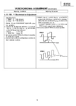
Page 112: ...VT 341 8X I T 5118X 1 WAVEFORMS 112 ...
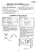
Page 115: ...SCHEMATIC DIAGRAM n VCR Main Unit r 7 I 1 I 2 I 3 I 4 I 5 I 6 115 ...
Page 119: ...D I c9 I n I u I m I n I GI I I I ...
Page 123: ...D I a I n I u I m I n I GI I I I ...
Page 124: ...11 I 12 I ...
Page 126: ...J l J I i _ _ _ ___ I _ _ n f f 7 I 8 I 9 I 10 I 11 I 12 126 ...
Page 152: ...VT 341 8X VT 5118X MECHANISM CHASSIS PARTS 152 ...
Page 155: ...H G F E D C B A CASSETTE HOUSING CONTROL PARTS 1 I 2 I 3 I 4 I 5 I 6 I 155 ...
Page 157: ...MECt 1 I 2 I 3 I 4 I 5 I 6 157 ...
Page 158: ...VT 341 8X VT 51 18X I I 7 I 8 I 9 I 10 I 11 I 12 I 158 ...
Page 161: ...H G F E D C B A VT 341 8X VT 5118X 1 2 I 3 I 4 I 5 I 6 161 ...
Page 162: ...VT 341 8X VT 51 18X I I 7 I 8 I 9 I 10 I 11 I 162 12 I ...
Page 163: ... 1 DEL VT 3418X CABINET AND MECHANICAL PARTS 0 II I L e e m I w F J 1 I 2 I 3 I 4 I 5 I 6 163 ...
Page 164: ... ...
Page 169: ...Memo m 169 ...
Page 170: ...S H A R P T98 19 S Printed in Japan 0 w s MW KD ...