
envelope
Head switching pulse
Figure
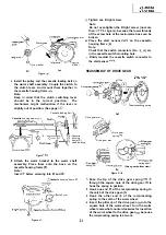
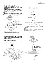
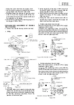
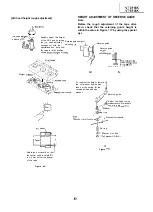
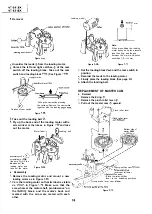
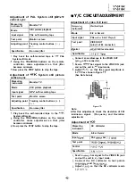
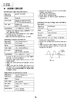
Adjustment of A/C head height and azimuth
a) Connect an oscilloscope to the audio output.
(Pin
of EL connector)
Use the alignment tape and play back its
audio 7
signal (monoscope pattern for
video signal). Adjust the azimuth adjusting
screw to obtain the maximum audio output
on an oscilloscope. (See Figure
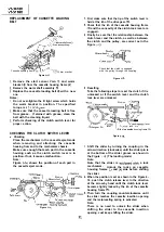
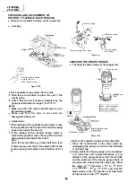
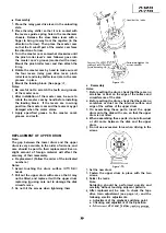
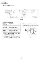
Use the alignment tape and play back its
audio 1
signal
bar for video signal)
and slowly rotate the A/C head height
adjusting nut with the special box driver to
obtain the maximum audio output.
Perform the adjustment in again.
After this adjustment, apply
to the
screws and nuts to fix them.
Azimuth adjusting
screw
Figure
Figure
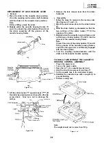
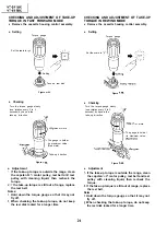
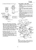
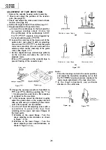
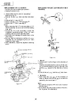
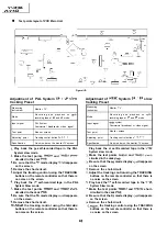
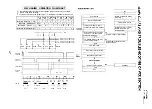
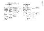
Adjustment of tape drive train and X-Position.
a) Connect the oscilloscope to the test points
for
envelope output.
Set the synchronism of the oscilloscope to EXT.
The
signal is to be triggered by
the head switching pulse
Play back the tape drive train alignment tape.
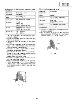
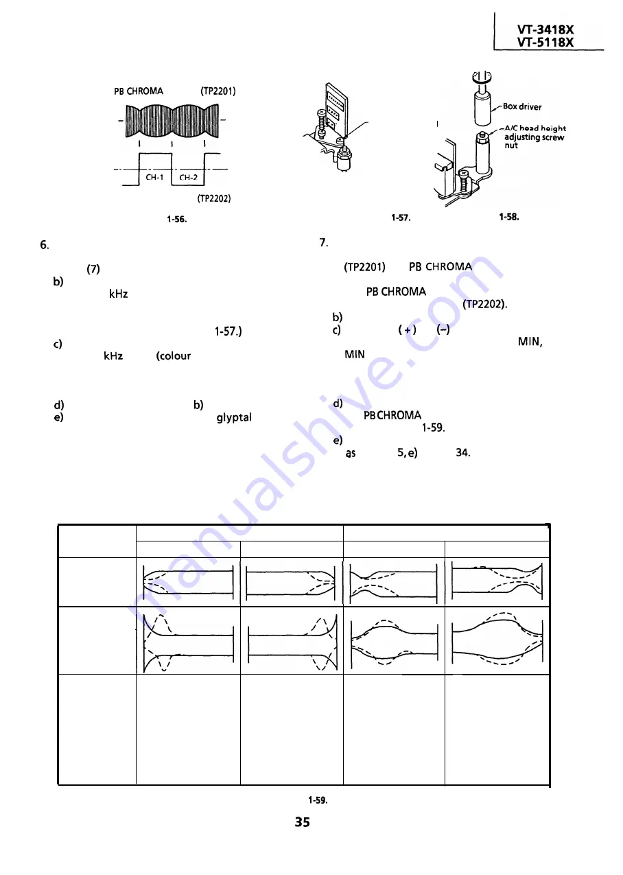
Push the
or
button to change the
envelope waveform from MAX to
and
to MAX. Adjust the guide roller’s height
on the supply and take-up sides with an
adjusting screw driver, to obtain an envelop
waveform that is as flat as possible.
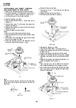
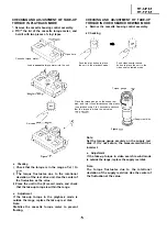
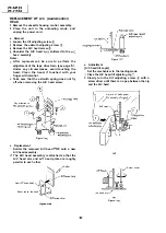
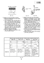
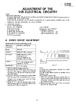
If the tape is above or below the helical lead,
the
waveform will take the shape
shown in Figure
Adjust for maximum flatness of the envelope
the step in page
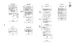
When the tape is above the helical lead.
When the tape is below the helical lead.
Supply side
Take-up side
Supply side
Take-up side
Supply side guide
Take-up side guide
Supply side guide
Take-up side guide
roller rotated in
roller rotated in
roller rotated in
roller rotated in
clockwise direction
clockwise direction
counterclockwise
counterclockwise
direction (raises guide
Adjustment
(lowers guide roller) to
(lowers guide roller) to
direction (raises guide
roller) to make the
flatten envelope.
flatten envelope.
roller) to make the
tape float above the
tape float above the
helical lead. The supply
helical lead.
side guide roller is
The take-up side guide
roller is then rotated in
then rotated in the
the clockwise direction
clockwise direction to
to flatten the
flatten the envelope.
envelope.
Figure
Summary of Contents for VT-3418X
Page 54: ...VT 341 8X VT 51 18X is z 0 Y Y c U T J 2 c 4 54 ...
Page 61: ...VT 341 8X VT 51 18X TROUBLESHOOTING OF TV SECTION I I I I 1 I I I I I I I ___ I iiE I b z 61 ...
Page 74: ...m 3418X i T 5118X VCJ AV UNIT 7 I 8 I 9 I 10 I 11 I 12 I 74 ...
Page 76: ...VT 341 8X VT 5118X VCJ AV UNIT I 7 I 8 I 9 I 10 I 11 I 12 1 76 ...
Page 78: ...PWB B V I D E O CHROMA J U N G L E 7 I 8 I 9 I 10 I 11 I 12 I 78 ...
Page 80: ...PWE 8 I 1 V I D E O CHROMA JUNGLE hr r I 7 I 8 I 9 I 10 I 11 I 12 I 80 ...
Page 86: ...VT 341 8X VT 5118X 7 I 8 I 9 I 10 I 11 I 12 I 86 ...
Page 88: ...rr J I I TUNER w2o1 m ...
Page 89: ...n 3 30 ...
Page 90: ...VT 341 8X VT 5118X VCJ AV UNIT DUNTK830 I WEV3 I I I m c I 7 I 8 I 9 I 10 1 11 I 12 I 90 ...
Page 92: ... VT 341 8X VT 51 18X DUNTK8302WEV 1 DUNTK8303WEV I I 7 I 8 I 9 I 10 I 11 I 12 I 92 ...
Page 94: ...VT 341 8X VT 5118X DUNTK8302WEV3 DUNTK8303WEV3 7 I 8 I 9 I 10 I 11 I 12 I 94 ...
Page 97: ... _ _ _ __ D I m I n I t3 I m I n I GI I I 1 ...
Page 98: ...Memo _ a _ _ 98 ...
Page 102: ...I REC I w r I I I CAPSTAN FG 7 I 8 I 9 I 10 I 11 I 12 1 102 ...
Page 106: ...CASSETTE SW REC TIP I ED M I I II DFfwPG I I I I I I I I I I I I ...
Page 110: ...VT 341 8X I VT 5118X 1 J 7 I 8 I 9 I 10 I 11 I 12 I 110 ...
Page 112: ...VT 341 8X I T 5118X 1 WAVEFORMS 112 ...
Page 115: ...SCHEMATIC DIAGRAM n VCR Main Unit r 7 I 1 I 2 I 3 I 4 I 5 I 6 115 ...
Page 119: ...D I c9 I n I u I m I n I GI I I I ...
Page 123: ...D I a I n I u I m I n I GI I I I ...
Page 124: ...11 I 12 I ...
Page 126: ...J l J I i _ _ _ ___ I _ _ n f f 7 I 8 I 9 I 10 I 11 I 12 126 ...
Page 152: ...VT 341 8X VT 5118X MECHANISM CHASSIS PARTS 152 ...
Page 155: ...H G F E D C B A CASSETTE HOUSING CONTROL PARTS 1 I 2 I 3 I 4 I 5 I 6 I 155 ...
Page 157: ...MECt 1 I 2 I 3 I 4 I 5 I 6 157 ...
Page 158: ...VT 341 8X VT 51 18X I I 7 I 8 I 9 I 10 I 11 I 12 I 158 ...
Page 161: ...H G F E D C B A VT 341 8X VT 5118X 1 2 I 3 I 4 I 5 I 6 161 ...
Page 162: ...VT 341 8X VT 51 18X I I 7 I 8 I 9 I 10 I 11 I 162 12 I ...
Page 163: ... 1 DEL VT 3418X CABINET AND MECHANICAL PARTS 0 II I L e e m I w F J 1 I 2 I 3 I 4 I 5 I 6 163 ...
Page 164: ... ...
Page 169: ...Memo m 169 ...
Page 170: ...S H A R P T98 19 S Printed in Japan 0 w s MW KD ...