
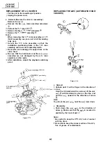
ADJUSTMENT OF THE
VCR ELECTRICAL CIRCUITRY
Notes:
Before the adjustment:
Electrical adjustments discussed here are often required after replacement of electronic
mechanical parts such as video heads.
Check that the mechanism and all electric components are in good working condition prior to the
adjustments, otherwise adjustments can not be completed.
l
Instruments required:
signal generator
e oscilloscope
Frequency counter
Blank video cassette tape
Screwdriver for adjustment
bar generator
voltmeter
@Alignment tape
Extension connector
AL AL)
n
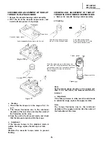
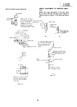
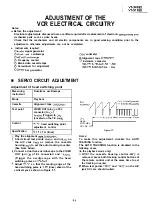
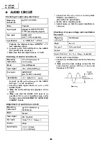
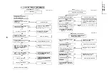
SERVO CIRCUIT ADJUSTMENT
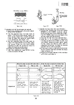
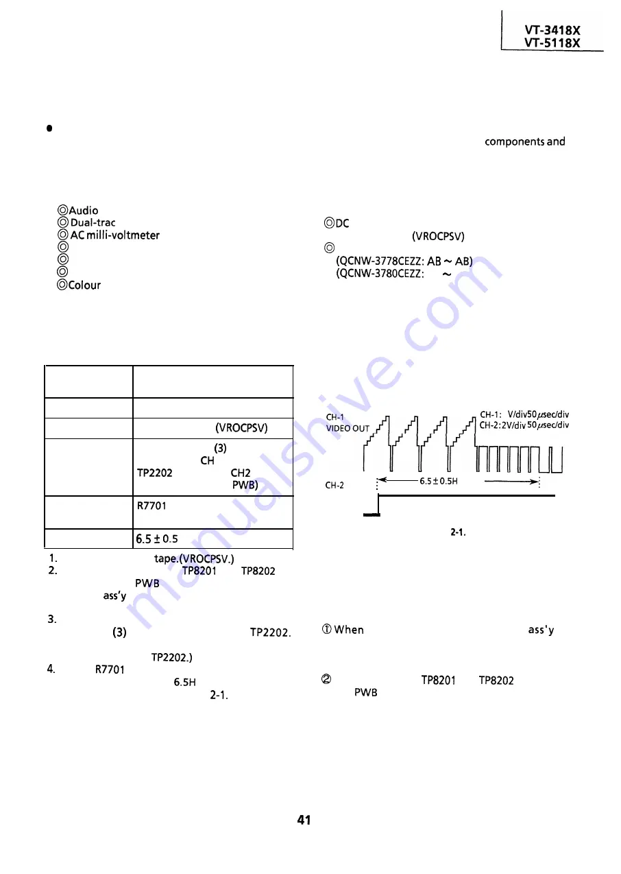
Adjustment of head switching point
Measuring
Dual-trace oscilloscope
instrument
Mode
Cassette
Test point
Playback
Alignment tape
VIDEO OUT (pin
of EL
connector) to
1
(Trigger) to
(Located on the Y/C
Control
head switching point
adjustment control
Specification
H (lines)
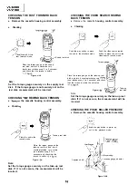
Play the alignment
Short circuit test points
and
on
the A/V Jack
or remove the cassette
housing
to set the auto tracking to center.
(See Note below)
Connect a dual trace oscilloscope to the VIDEO
OUT (pin
of EL connector) and
(Trigger the oscilloscope with the head
switching pulse on
Adjust
so that the leading edge of the
head switching pulse is
(lines) ahead of the
vertical sync as shown in Figure
1
HEAD .
SWITCHING
P U L S E
(lines)
V-sync.
Figure
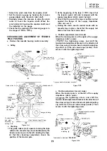
Notes:
To make this adjustment, disable the AUTO
TRACKING function.
The AUTO TRACKING function is disabled in the
following cases.
(In the playback mode only.)
the cassette housing control
is
removed, press both tracking control buttons of
the remote control unit at the same time to set
the tracking in center.
When test points
and
on the A/V
jack
are short-circuited.
Summary of Contents for VT-3418X
Page 54: ...VT 341 8X VT 51 18X is z 0 Y Y c U T J 2 c 4 54 ...
Page 61: ...VT 341 8X VT 51 18X TROUBLESHOOTING OF TV SECTION I I I I 1 I I I I I I I ___ I iiE I b z 61 ...
Page 74: ...m 3418X i T 5118X VCJ AV UNIT 7 I 8 I 9 I 10 I 11 I 12 I 74 ...
Page 76: ...VT 341 8X VT 5118X VCJ AV UNIT I 7 I 8 I 9 I 10 I 11 I 12 1 76 ...
Page 78: ...PWB B V I D E O CHROMA J U N G L E 7 I 8 I 9 I 10 I 11 I 12 I 78 ...
Page 80: ...PWE 8 I 1 V I D E O CHROMA JUNGLE hr r I 7 I 8 I 9 I 10 I 11 I 12 I 80 ...
Page 86: ...VT 341 8X VT 5118X 7 I 8 I 9 I 10 I 11 I 12 I 86 ...
Page 88: ...rr J I I TUNER w2o1 m ...
Page 89: ...n 3 30 ...
Page 90: ...VT 341 8X VT 5118X VCJ AV UNIT DUNTK830 I WEV3 I I I m c I 7 I 8 I 9 I 10 1 11 I 12 I 90 ...
Page 92: ... VT 341 8X VT 51 18X DUNTK8302WEV 1 DUNTK8303WEV I I 7 I 8 I 9 I 10 I 11 I 12 I 92 ...
Page 94: ...VT 341 8X VT 5118X DUNTK8302WEV3 DUNTK8303WEV3 7 I 8 I 9 I 10 I 11 I 12 I 94 ...
Page 97: ... _ _ _ __ D I m I n I t3 I m I n I GI I I 1 ...
Page 98: ...Memo _ a _ _ 98 ...
Page 102: ...I REC I w r I I I CAPSTAN FG 7 I 8 I 9 I 10 I 11 I 12 1 102 ...
Page 106: ...CASSETTE SW REC TIP I ED M I I II DFfwPG I I I I I I I I I I I I ...
Page 110: ...VT 341 8X I VT 5118X 1 J 7 I 8 I 9 I 10 I 11 I 12 I 110 ...
Page 112: ...VT 341 8X I T 5118X 1 WAVEFORMS 112 ...
Page 115: ...SCHEMATIC DIAGRAM n VCR Main Unit r 7 I 1 I 2 I 3 I 4 I 5 I 6 115 ...
Page 119: ...D I c9 I n I u I m I n I GI I I I ...
Page 123: ...D I a I n I u I m I n I GI I I I ...
Page 124: ...11 I 12 I ...
Page 126: ...J l J I i _ _ _ ___ I _ _ n f f 7 I 8 I 9 I 10 I 11 I 12 126 ...
Page 152: ...VT 341 8X VT 5118X MECHANISM CHASSIS PARTS 152 ...
Page 155: ...H G F E D C B A CASSETTE HOUSING CONTROL PARTS 1 I 2 I 3 I 4 I 5 I 6 I 155 ...
Page 157: ...MECt 1 I 2 I 3 I 4 I 5 I 6 157 ...
Page 158: ...VT 341 8X VT 51 18X I I 7 I 8 I 9 I 10 I 11 I 12 I 158 ...
Page 161: ...H G F E D C B A VT 341 8X VT 5118X 1 2 I 3 I 4 I 5 I 6 161 ...
Page 162: ...VT 341 8X VT 51 18X I I 7 I 8 I 9 I 10 I 11 I 162 12 I ...
Page 163: ... 1 DEL VT 3418X CABINET AND MECHANICAL PARTS 0 II I L e e m I w F J 1 I 2 I 3 I 4 I 5 I 6 163 ...
Page 164: ... ...
Page 169: ...Memo m 169 ...
Page 170: ...S H A R P T98 19 S Printed in Japan 0 w s MW KD ...