


50
VC-G20SM/G200SM
VC-G201SM/G401SM
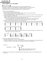
REPLACEMENT OF IC710(E
2
PROM)
Servicing precautions
When the IC710(E
2
PROM) has been replaced, make the following reprogramming.
Depending on models, the IC710(E
2
PROM) has been factory adjusted for it s memory function.
It s therefore necessary to reprogram the memory function for the model in question.
Note that the servo circuit requires readjustments for the slow and still modes.
1. Memory function reprogramming.
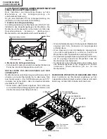
a. Check the power off.(Power is standby mode)
b. Make for moment short-circuit test point(TP801), located at the front side on the main PWB.
Be sure that all the display light up into the TEST mode.
c. Using the C) AND (—) buttons, select the right function numbers from JP0 to JP39, which appear in the
display, referring to the E
2
PROM map.
Press the DISPLAY button to pickup the functions(ON) and the CLEAR button to discard the functions(OFF).
DISPLAY and CLEAR buttons, are located on the remote control unit.
∗
when the DISPLAY button has been pressed (ON), the memory function number starts flashing.
∗
when the CLEAR button has been pressed (OFF), the memory function number lights up.
d. Example : "ON" and "OFF" are taken as "1" and "0" respectively.
The numbers JP0 to JP39 are divided into four groups and each group s setting is displayed in hexadecimal notation.
JP27 JP26 JP25 JP24
1
1
0
0
↓
C
JP23 JP22 JP21 JP20
0
0
0
0
↓
0
JP19 JP18 JP17 JP16
0
0
0
0
↓
0
JP15 JP14 JP13 JP12
0
1
0
0
↓
4
JP11 JP10 JP9 JP8
0
0
1
1
↓
3
JP7 JP6 JP5 JP4
0
0
0
0
↓
0
JP3 JP2 JP1 JP0
0
0
0
0
↓
0
Also recording level preset number selected from the ten keys on the remote control unit which appear in the
LCD display, referring to the E
2
PROM map.
JP39 JP38 JP37 JP36
0
0
0
0
↓
0
JP35 JP34 JP33 JP32
0
0
0
1
↓
1
JP31 JP30 JP29 JP28
0
0
0
0
↓
0
SP n
∗
∗
↑
selection from the
ten keys.
(from "0" to "7")
EP n
∗
∗
↑
selection from the
ten keys.
(from "0" to "7")
Out lights
blank
SP p
∗
∗
↑
selection from the
ten keys.
(from "0" to "7")
LP p
∗
∗
↑
selection from the
ten keys.
(from "0" to "7")
2. Memory recording preset level reprogramming.
a. Similarly to the above step 1-a and 1-b the same operate.
b. Using the CHANNEL (+) AND (-) buttons, select the right function numbers continued from recording preset number
as has been JP0~JP39, which appear in the LCD display, referring to the E
2
PROM map.
3. Example :
System
p : PAL
n : NTSC
↓
Tape speed
→
LP or EP
n
∗
∗
↑
↑
Chrominance preset number. (from "0" to "7")
Luminance preset number. (from "0" to "7")
3. Finally make for a moment short-circuit test point(TP801), located at the front side on the main PWB to clear the
TEST mode.
↑
↑
↑
↑
Summary of Contents for VC-G200SM
Page 103: ...103 VC G20SM G200SM VC G201SM G401SM ...
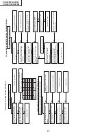
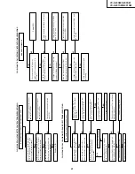
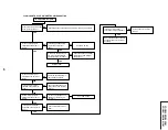
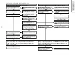
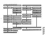
Page 104: ...104 VC G20SM G200SM VC G201SM G401SM SIGNAL FLOW BLOCK DIAGRAM SIGNALVERLAUF BLOCKSCHALTBILD ...
Page 113: ...113 10 11 12 13 14 15 16 17 18 19 VC G20SM G200SM VC G201SM G401SM ...
Page 115: ...115 10 11 12 13 14 15 16 17 18 19 VC G20SM G200SM VC G201SM G401SM ...
Page 117: ...117 10 11 12 13 14 15 16 17 18 19 VC G20SM G200SM VC G201SM G401SM ...
Page 119: ...119 10 11 12 13 14 15 16 17 18 19 VC G20SM G200SM VC G201SM G401SM ...
Page 123: ...123 10 11 12 13 14 15 16 17 18 19 VC G20SM G200SM VC G201SM G401SM ...
Page 125: ...125 10 11 12 13 14 15 16 17 18 19 VC G20SM G200SM VC G201SM G401SM ...
Page 127: ...127 10 11 12 13 14 15 16 17 18 19 VC G20SM G200SM VC G201SM G401SM ...


