


39
VC-G20SM/G200SM
VC-G201SM/G401SM
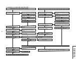
7. ELECTRICAL
TROUBLESHOOTING
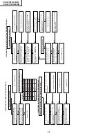
FLOW CHART NO.1 POWER TROUBLESHOOTING(1)
No power
Unplug the
AC power cord.
Replug it a few minutes later
.
See FLOW CHAR
T
NO.2 POWER
TROUBLESHOOTING (2).
YES
YES
YES
YES
NO
NO
NO
NO
Is the fuse good?
Replace fuse.
Is
A
T
5V voltage line normal?
Check primary circuit.
Are
A
T
39V
, A
T
25V and
A
T
12V lines
normal?
Check each rectifier circuits and
short-circuit of secondary circuit.
Is "H" level applied at pin(1) of
system CTL
circuit IC701?
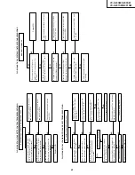
FLOW CHART NO.3 POWER TROUBLESHOOTING(3)
In case of abnormal noise(sound)
Check
D931, D9332, D933
and D934.
The
D931, D9332, D933
and
D934 as a result of check
if poor the replace.
NO
FLOW CHART NO.2 POWER TROUBLESHOOTING(2)
In case of Fuse(F901) blown out.
Replace F901, Q901 and R904.
Check D901, D902, D903 and D904
as a result of check, if poor
, replace
at the same time.
Check short-circuit or leak of
D931, D9332, D933, D934 and
secondary circuit.
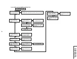
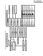
FLOW CHART NO.5 TIMER TROUBLESHOOTING (1)
The LCD display fails to light up.
Is the supply voltage of 5V fed to
pin(37) of IC8001?
Check
A
T
5V line.
Is the supply voltage of 3.4V
, 1.7V
feed to pin(38) and pin(39) of IC8001?
Check pin(38), (39) of IC8001
and peripheral circuits.
Is it possible to confirm signals
LCD RESET
, LCD CS, LCD CLOCK
and LCD DA
T
A
on the pins(36),
(42), (43) and (44) of IC8001?
Are the segment signals
supplied to the LCD display
(LC8001) fromthe driver IC
(IC8001)?
Check peripheral circuit of pin(41)
of IC8001.
Check that the LCD display is
free from damages such as
crack.
Replace IC8001.
YES
YES
YES
YES
NO
NO
NO
NO
NO
YES
YES
YES
NO
NO
NO
FLOW CHART NO.4 POWER TROUBLESHOOTING(4)
In case of output voltage at low level.
Check peripheral circuits IC901,
IC903, C9336, R930, R932 and
R933.
The IC901, IC903, C9336, R930,
R932 and R933 as a result
of check, if poor the replace.
Check IC901 and peripheral
circuits.
Replace Q902.
Check short-circuit or leak of
T901.
Replace T901.
Check primary circuit and peripheral
circuit of Q901 and Q902.
Check the signal line between
IC701 and IC8001.
YES
IC8001 present?
Is the OSC signal at pin(41) of
Summary of Contents for VC-G200SM
Page 103: ...103 VC G20SM G200SM VC G201SM G401SM ...
Page 104: ...104 VC G20SM G200SM VC G201SM G401SM SIGNAL FLOW BLOCK DIAGRAM SIGNALVERLAUF BLOCKSCHALTBILD ...
Page 113: ...113 10 11 12 13 14 15 16 17 18 19 VC G20SM G200SM VC G201SM G401SM ...
Page 115: ...115 10 11 12 13 14 15 16 17 18 19 VC G20SM G200SM VC G201SM G401SM ...
Page 117: ...117 10 11 12 13 14 15 16 17 18 19 VC G20SM G200SM VC G201SM G401SM ...
Page 119: ...119 10 11 12 13 14 15 16 17 18 19 VC G20SM G200SM VC G201SM G401SM ...
Page 123: ...123 10 11 12 13 14 15 16 17 18 19 VC G20SM G200SM VC G201SM G401SM ...
Page 125: ...125 10 11 12 13 14 15 16 17 18 19 VC G20SM G200SM VC G201SM G401SM ...
Page 127: ...127 10 11 12 13 14 15 16 17 18 19 VC G20SM G200SM VC G201SM G401SM ...


