


13
VC-G20SM/G200SM
VC-G201SM/G401SM
Notes:
1. Hold the torque gauge by hand so that it is not moved.
2. Do not keep the reel disk in lock state. Do not allow long-
time measurement.
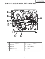
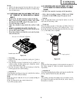
4-8 CHECKING AND ADJUSTMENT OF TAKE-
UP TORQUE IN RECORD/PLAYBACK
MODE
•
Remove the cassette housing control assembly.
•
After short-circuiting between TP803 and TP802
provided at main PWB, plug in the power cord.
•
Turn off the power switch.
•
Open the cassette torque meter lid, and fix it with
tape.
•
Load the cassette torque meter into the unit.
•
Put the weight (500g) on the cassette torque meter.
•
Turn on the power switch.
•
Press the picture record button, and set LP picture
record mode (x2).
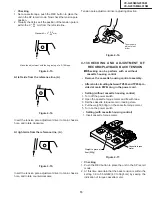
4-9 CHECKING AND ADJUSTMENT OF TAKE-
UP TORQUE IN VIDEO SEARCH REWIND
MODE
•
Remove the cassette housing control assembly.
•
After short-circuiting between TP803 and TP802
provided at main PWB, plug in the power cord.
•
Setting
Press the playback button and rewind button to set the
video search rewinding mode.
•
Checking
Place the torque gauge on the supply reel disk, and turn it
counterclockwise very slowly (one rotation every 1 to 2
seconds) and check that the torque is within the set value
14.1 ± 3.5mN
⋅
m. (144 ± 35gf
⋅
cm)
Set value LP 6.9
mN
⋅
m (70
gf
⋅
cm)
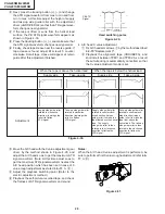
Figure 4-8.
• Checking
1. Make sure that value is within the setting 6.9 mN·m
(70 gf·cm).
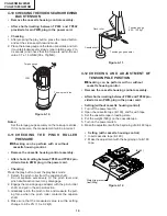
2. The winding-up torque fluctuates due to variation of
rotation torque of limiter pulley ass'y. Read the center
value of fluctuation as setting.
3. Set the LP record mode (x2) and make sure that the
winding-up torque is within setting.
• Adjustment
If the playback winding-up torque is not within the setting,
replace the limiter pulley assembly.
Note:
When the torque cassette is set, put a weight (500g) to
prevent rise.
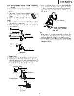
When the cassette torque meter is taken out.
Turn off the power switch.
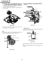
Figure 4-9.
Note:
Surely put the torque gauge on the reel disk to measure. If
the torque gauge is raised, accurate measurement is
impossible.
•
Adjustment
If the rewinding playback winding-up torque is not within the
setting, replace the limiter pulley assembly.
Note:
The winding-up torque fluctuates due to variation of rota-
tion torque of supply reel disk. Read the center value of
fluctuation as setting.
Torque gauge
Supply reel disk
CCW
+20
–25
+2.0
–2.5
+2.0
–2.5
+20
–25
500g
Cassette torque meter
Summary of Contents for VC-G200SM
Page 103: ...103 VC G20SM G200SM VC G201SM G401SM ...
Page 104: ...104 VC G20SM G200SM VC G201SM G401SM SIGNAL FLOW BLOCK DIAGRAM SIGNALVERLAUF BLOCKSCHALTBILD ...
Page 113: ...113 10 11 12 13 14 15 16 17 18 19 VC G20SM G200SM VC G201SM G401SM ...
Page 115: ...115 10 11 12 13 14 15 16 17 18 19 VC G20SM G200SM VC G201SM G401SM ...
Page 117: ...117 10 11 12 13 14 15 16 17 18 19 VC G20SM G200SM VC G201SM G401SM ...
Page 119: ...119 10 11 12 13 14 15 16 17 18 19 VC G20SM G200SM VC G201SM G401SM ...
Page 123: ...123 10 11 12 13 14 15 16 17 18 19 VC G20SM G200SM VC G201SM G401SM ...
Page 125: ...125 10 11 12 13 14 15 16 17 18 19 VC G20SM G200SM VC G201SM G401SM ...
Page 127: ...127 10 11 12 13 14 15 16 17 18 19 VC G20SM G200SM VC G201SM G401SM ...


