


18
VC-G20SM/G200SM
VC-G201SM/G401SM
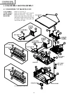
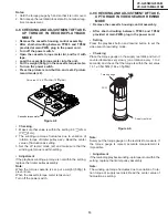
4-17 ADJUSTMENT OF TAPE DRIVE TRAIN
1. Tape run rough adjustment
1
Check and adjust the position of the tension pole.
(See 4-12.)
2
Check and adjust the video search rewind back
tension. (See 4-10.)
3
Connect the oscilloscope to the test point for PB ATR
signal output (TP201). Set the synchronism of the
oscilloscope to EXT. The PB ATR signal is to be
triggered by the head switching pulse (TP202).
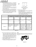
4
Set the alignment tape (VROUBZFS) to play.
Figure 4-26.
5
Press the tracking button (+), (–) and change the
ATR signal waveform from max to min and from min
to max. At this time make sure that the ATR signal
waveform changes nearly parallel.
6
Unless the ATR signal waveform changes nearly
parallel, adjust the height of supply side and take-up
side guide roller so that the envelope waveform
changes nearly parallel. (For ATR signal adjustment
procedure refer to Figure 4-30.)
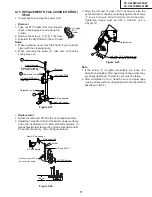
7
Turn the tilt screw to remove the tape crease at the
fixing guide flange.
Playback the tape and check for tape crease at the
fixing guide flange.
(1) If there is no tape crease
Turn the tilt screw clockwise so that tape crease
appears once at the flange, and then return the tilt
screw so that the crease disappears.
(2) If there is tape crease
Turn counterclockwise the tilt screw so that the
tape crease disappears.
(Reference) If the tilt screw is turned clockwise
crease appears at the lower flange.
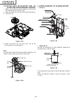
Guide roller
Cassette Tape
Figure 4-24.
Figure 4-25.
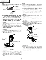
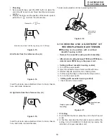
Tape
0.3mm
A/C head
• Adjustment
Adjust the height screw
visually so that the control head is
visible 0.3mm below the bottom of the tape.
1. Set the cassette tape in the unit.
2. Press the PLAY button to put the unit in the playback
mode.
3. Roughly adjust the height of the A/C head by turning the
height screw until the tape is in the position shown
below.
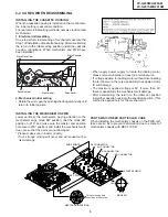
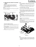
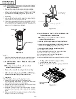
4-16 A/C HEAD HEIGHT ROUGH ADJUSTMENT
• Setting
Mechanism chassis
Cassette tape
Height screw
TiH screw
Azimuth screw
500g
Weight to prevent
float (500g)
Summary of Contents for VC-G200SM
Page 103: ...103 VC G20SM G200SM VC G201SM G401SM ...
Page 104: ...104 VC G20SM G200SM VC G201SM G401SM SIGNAL FLOW BLOCK DIAGRAM SIGNALVERLAUF BLOCKSCHALTBILD ...
Page 113: ...113 10 11 12 13 14 15 16 17 18 19 VC G20SM G200SM VC G201SM G401SM ...
Page 115: ...115 10 11 12 13 14 15 16 17 18 19 VC G20SM G200SM VC G201SM G401SM ...
Page 117: ...117 10 11 12 13 14 15 16 17 18 19 VC G20SM G200SM VC G201SM G401SM ...
Page 119: ...119 10 11 12 13 14 15 16 17 18 19 VC G20SM G200SM VC G201SM G401SM ...
Page 123: ...123 10 11 12 13 14 15 16 17 18 19 VC G20SM G200SM VC G201SM G401SM ...
Page 125: ...125 10 11 12 13 14 15 16 17 18 19 VC G20SM G200SM VC G201SM G401SM ...
Page 127: ...127 10 11 12 13 14 15 16 17 18 19 VC G20SM G200SM VC G201SM G401SM ...


