


2
VC-G20SM/G200SM
VC-G201SM/G401SM
PRECAUTIONS IN PART
REPLACEMENT
When servicing the unit with power on, be careful
to the section marked white all over.
This is the primary power circuit which is live.
When checking the soldering side in the tape travel
mode, make sure first that the tape has been loaded and
then turn over the PWB with due care to the primary
power circuit.
Make readjustment, if needed after replacement of part,
with the mechanism and its PWB in position in the main
frame.
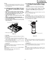
(1) Start and end sensors: Q701 and Q702
Insert the sensor's projection deep into the upper
hole of the holder . Referring to the PWB, fix the
sensors tight enough.
(2) Photocoupler: IC901 and IC902
Refer to the symbol on the PWB and the anode
marking of the part.
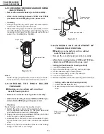
(3) Cam switches A and B : S704
Adjust the notch of the part to the white marker of the
symbol on the PWB. Do not allow any looseness.
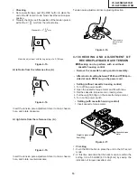
(4) Take-up and supply sensors : D706 and
D707
Be careful not to confuse the setting direction of the
parts in reference to the symbols on the PWB. Do not
allow any looseness.
VORSICHTSMASSNAHMEN BEIM
AUSWECHSELN VON TEILEN
Bei Wartungsarbeiten am Gerät mit eingeschalteter
Stromversorgung ist besonders auf den weiß
markierten Abschnitt zu achten.
Es handelt sich um den Primärstromkreis, der
spannungsführend ist.
Beim Überprüfen der Lötseite im Bandlaufmodus muß
zunächst sichergestellt werden, daß das Band eingezogen
wurde. Dann die Platine unter entsprechender Beachtung
des Primärstromkreises umdrehen.
Eine ggf. erforderliche Neueinstellung nach dem
Auswechseln von Teilen druchführen während sich
Bandlaufwerk und Platine im Hauptrahmen befinden.
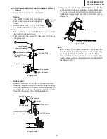
(1) Start- und Endsensoren: Q701 und Q702
Das hervorstehende Teil des Sensors tief in die
obere Öffnung des Halter stecken. Die Sensoren in
Bezug auf die Platine ausreichend befestigen.
(2) Fotokoppler: IC901 und IC902
Siehe das Symbol auf der Platine und die
Anodenkennzeichnung des Teils.
(3) Nockenschalter A und B: S704
Die Kerbe des Teils mit der weißen Markierung des
Symbols auf der Platine ausrichten. Die Teile müssen
fest sitzen.
(4) Aufwickel- und Abwickelsensoren : D706
und D707
Darauf achten, daß die Ausrichtung der Teile in
Bezug auf die Symbole auf der Platine nicht
vertauscht wird.
Summary of Contents for VC-G200SM
Page 103: ...103 VC G20SM G200SM VC G201SM G401SM ...
Page 104: ...104 VC G20SM G200SM VC G201SM G401SM SIGNAL FLOW BLOCK DIAGRAM SIGNALVERLAUF BLOCKSCHALTBILD ...
Page 113: ...113 10 11 12 13 14 15 16 17 18 19 VC G20SM G200SM VC G201SM G401SM ...
Page 115: ...115 10 11 12 13 14 15 16 17 18 19 VC G20SM G200SM VC G201SM G401SM ...
Page 117: ...117 10 11 12 13 14 15 16 17 18 19 VC G20SM G200SM VC G201SM G401SM ...
Page 119: ...119 10 11 12 13 14 15 16 17 18 19 VC G20SM G200SM VC G201SM G401SM ...
Page 123: ...123 10 11 12 13 14 15 16 17 18 19 VC G20SM G200SM VC G201SM G401SM ...
Page 125: ...125 10 11 12 13 14 15 16 17 18 19 VC G20SM G200SM VC G201SM G401SM ...
Page 127: ...127 10 11 12 13 14 15 16 17 18 19 VC G20SM G200SM VC G201SM G401SM ...


