MX-FNX9 ELECTRICAL SECTION 10 – 5
This circuit controls rotation/stop and the rotating direction of the staple shift motor (FSM) and the motor current, and is composed of the
CPU (IC10), the DA converter (IC11), and the constant-current chopper system driver IC (IC4). The motor rotating speed and the rotating
direction are controlled with the stepping motor drive excitement pattern signal (ST_MOT_PA, PB, EA, EB) outputted from the CPU (IC10-
45, 46, 47, 48pin).
The analog signal (ST_MOT_REF) outputted from the DA converter (IC11-18pin) is divided into a certain voltage with R64 and R65. The
divided voltage is inputted to IC4-3, 4pin to set the motor current value. The logic of the standby signal (MOT_STY) outputted from the DA
converter (IC11-7pin) is H when the motor can be operated (READY).
5)
Alignment motor F (FFJM) drive circuit
6)
Alignment motor R (FRJM) drive circuit
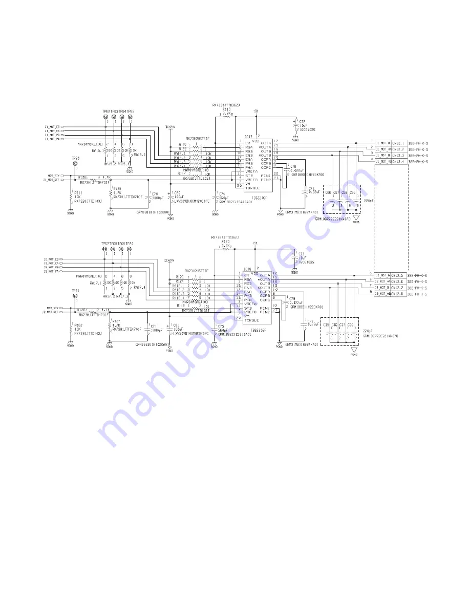
This circuit controls rotation/stop and the rotating direction of the alignment motor F (FFJM) and the motor current, and is composed of the
CPU (IC10), the DA converter (IC11), and the constant-current chopper system driver IC (IC17). The motor rotating speed and the rotating
direction are controlled with the stepping motor drive excitement pattern signal (J1_MOT_PA, PB, EA, EB) outputted from the CPU (IC10-
49, 50, 51, 52pin).
The analog signal (J1_MOT_REF) outputted from the DA converter (IC11-19pin) is divided into a certain voltage with R125 and R126. The
divided voltage is inputted to IC17-3, 4pin to set the motor current value. The logic of the standby signal (MOT_STY) outputted from the
DA converter (IC11-7pin) is H when the motor can be operated (READY state).
This circuit controls rotation/stop and the rotating direction of the alignment motor R (FRJM) and the motor current, and is composed of the
CPU (IC10), the DA converter (IC11), and the constant-current chopper system driver IC (IC18). The motor rotating speed and the rotating
direction are controlled with the stepping motor drive excitement pattern signal (J2_MOT_PA, PB, EA, EB) outputted from the CPU (IC10-
53, 54, 55, 56pin).
The analog signal (J2_MOT_REF) outputted from the DA converter (IC11-2pin) is divided into a certain voltage with R127 and R128. The
divided voltage is inputted to IC18-3, 4pin to set the motor current value. The logic of the standby signal (MOT_STY) outputted from the
DA converter (IC11-7pin) is H when the motor can be operated (READY state).
Alignment motor F (FFJM)
Not
installed
Not installed
Alignment motor R (FRJM)


