background image

LL-T1512W

4 – 1

CHAPTER 4. TROUBLESHOOTING

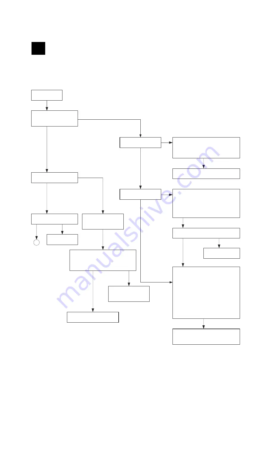
No power supply

Does LED turns on in green 
when power switch is turned 
on?

No

No

No

No

No

No

LED turns on in red?

Yes

Yes

Yes

Yes

Yes

Yes

Yes

*  Check LED for breakage.
*  Check cable for disconnection.

Replace any unit (main PWB, SW PWB, cable) 
which shows any defect, with a new one.

1) PC is turned off?
2) RGB cable is disconnected?
3) Synchronizing signal is output from RGB 

cable?

Check whether the unit is in power save 
mode (synchronizing signal is not input.).

Synchronizing signal is input to main PWB?

Replace RGB cable 
with a new one.

LED turns on in orange?

Check power input system.

1) AC adapter
   *  Normal?
   *  Connected properly?
2) Blown out fuse (F1, F2) ?
3) Each signal of 5V, D3, 3V, PVDD, 

AVDD1.8V is output ?

4) LED
   *  Check LED for breakage.
   *  Check the path between CN10 and 

IC22.

   *  Check the cable for disconnection.

Replace any defective unit.
[ 1) Adapter, 2) A Main PWB, 3) Switch 
PWB, ] with a new one.

Backlight turns ON?

Check for RGB cable input 
signal.

Replace RGB cable.

Normal

Normal

Normal

Defective

Defective

*  Check inverter block of main PWB.
Note: Use caution when checking output 

side because it has a high voltage. 

Replace LCD module lamp with 
a new one.

Replace main PWB 
unit with a new one.

A

Check each signal of 
BL_ON,+12V,BRI(150Hz,
Duty 15~65%)

Summary of Contents for LL-T1512W

Page 1: ...ety of the set Be sure to replace these parts with specified ones for maintaining the safety and performance of the set Top and Bottom of a Page 38 1mm 00ZLLT1512WSE LCD COLOR MONITOR MODEL LL T1512W LL T1512W CHAPTER 1 CHAPTER 2 CHAPTER 3 CHAPTER 4 CHAPTER 5 OUTLINE OF THE PRODUCT NOMENCLATURE AND FUNCTION 1 1 CONNECTION ADJUSTMENT OPERATION AND FUNCTIONS 2 1 DISASSEMBLY AND ASSEMBLY 3 1 TROUBLES...

Page 2: ...USB standard Rev 1 1 Bus powered type Tilting and Swiveling Tilt Approx 0 30 Swivel Left right total 90 Turn table type Power supply AC100 240V 50 60Hz Use special AC adapter type NL A56J of Sharp Corporation Operating temperature 5 35 C Power consumption Maximum 29W Stand by state 2 6W Use special AC adapter Dimensions W u D u H 370 mm u 150 mm u 355 mm Weight excluding AC adapter Approx 4 4 kg A...

Page 3: ...gement DDC Plug Play This monitor supports the VESA DDC Display Data Channel stan dard DDC is a signal standard for carrying out Plug Play functions on the monitor or PC It transfers information such as degree of resolution between the monitor and PC You can use this function if your PC is DDC compliant and if it is set so that it can detect the Plug Play monitor There are many varieties of DDC du...

Page 4: ...nector Remove the cover to see DC IN connector The AC adapter is connected here H Analog signal input Remove the cover to see Analog signal input connector Analog RGB signal connectorcable had been connected when shipping out this monitor I AC adapter AC adapter is mounted inside the cover J Analog RGB signal cable Connecting to Analog RGB output connector on a computer K DVI D input connector Rem...

Page 5: ...Pull slowly the upper sides of cover toward you while pushing the marks 3 Remove the cover c Pull slowly toward you while pushing both inner sides of the cover 4 Mounting the AC adapter 1 Bend lightly the root part of the cord Do not over bend the cord 2 Insert the root part of outlet cord until it goes out partly from the round hole And then slowly put down the AC adapter Please check whether AC ...

Page 6: ... cable through the opening of the cover and insert the hooks each side into projection 2 Push slowly the upper side of the cover until the hooks click into place 8 Close the cover a 1 Insert the three hooks into the slit 2 Push slowly both sides of the cover until the three hooks click into place 9 Connect the AC cord to the AC adapter inlet and plug into AC out let Note When you remove the cover ...

Page 7: ...o overly bend the cable or add stress onto the cable as this could lead to malfunction TURNING THE POWER ON 1 Press the monitor s POWER button 2 Turn on the computer The power LED will be lit green and the screen will display an image SELECTING THE TYPE OF INPUT CONNECTOR Pressing INPUT button to toggle input connector TURNING THE POWER OFF 1 Turn the computer off 2 Press the monitor s POWER butto...

Page 8: ...nd carefully 3 Remove the rear covers a b c in following the instructions given in page 12 4 Remove AC adapter from the stand 1 Disconnect the plug from DC IN connector 2 Remove the cord from hook and the cord holder 3 While lifting AC adapter s cord root side slide it toward the round opening and then pull toward you to remove AC adapter 5 Remove the four screws and then remove the stand from the...

Page 9: ...8 5 or above When using the ColorSync profile please set the WHITE BALANCE to STD and the COLOR MODE to OFF About installing procedure of profile please see operation manual 4 ADJUSTMENT 2 1 BEFORE ADJUSTING THE SCREEN DISPLAY For analog signal 1 First perform an automatic adjustment 2 Perform manual adjustment where necessary For digital signal The monitor can generally be used without adjustment...

Page 10: ... disabled ADJUSTMENT MENU RESET Resetting ADJUSTMENT Menu for Analog signal The values in ADJUSTMENT menu can be returned to their original ex factory values 1 Turn on the monitor power 2 Press the MENU button and the e button simultaneously When RESET appears on the screen the reset is complete Resetting all adjustment values All adjustment values can be returned to their original ex factory val ...

Page 11: ...e screen very bright 2 MANUAL SCREEN ADJUSTMENT Adjustments can be made using On Screen Display OSD Menu pro vided Press the MENU button The ADJUSTMENT Menu will be displayed At this point relevant menu options can be adjusted Each time the MENU button is pressed the next menu is selected ADJUSTMENT 3 GAIN CONTROL 3 WHITE BALANCE 3 MODE SELECT 3 OSD Menu disappears Note The OSD Menu automatically ...

Page 12: ... CONTRAST To go to the next menu MENU button COOL Color tone bluer than standard Color tone slightly bluer than standard STD Color tone standard setting Color tone slightly redder than standard WARM Color tone redder than standard USER R CONTRAST e button for blue green d button for red G CONTRAST e button for purple d button for green B CONTRAST e button for yellow d button for blue MODE SELECT M...

Page 13: ...rd setting Color tone slightly redder than standard WARM Color tone redder than standard USER R CONTRAST e button for blue green d button for red G CONTRAST e button for purple d button for green B CONTRAST e button for yellow d button for blue MODE SELECT Menu Notes Depending on the resolution of the input signal even if menu options can be selected the display may not change To choose a menu opt...

Page 14: ...n 0 255 AUTO n Menu3 WHITE BALANCE n COOL n STD n WARM 5 stages USER R n G n B 0 255 Menu4 MODE SELECT OSD H POSITION n 0 OSD V POSITION n 0 400 LINES n 640 n 720 EXPAND n ON1 Aspect ratio n ON2 Full screen SCALING n 1 5 COLOR MODE sRGB n STD LANGUAGE n 7 language DEUTSCH ENGLISH ESPANOL FRANCAIS ITALIANO NETHERLAND SVENSKA BRIGHT BRIGHT onetouch n AUTO n LOW n MID n HIGH COLOR MODE n STD n sRGB n...

Page 15: ...eparate angle 3 switch board 4 and key bottom 5 6 from the LCD block 4 Remove the four screws C to separate the LCD module 7 from the LCD block 5 Remove the three screws D to separate the USB board 8 3 LCD MODULE SECTION 1 Remove the four screws A to separate the bracket 1 2 Remove the seven screws B to separate the bracket 2 3 Remove the eight cable 3 4 Remove the three screws C to separate the m...

Page 16: ... PWB Replace RGB cable with a new one LED turns on in orange Check power input system 1 AC adapter Normal Connected properly 2 Blown out fuse F1 F2 3 Each signal of 5V D3 3V PVDD AVDD1 8V is output 4 LED Check LED for breakage Check the path between CN10 and IC22 Check the cable for disconnection Replace any defective unit 1 Adapter 2 A Main PWB 3 Switch PWB with a new one Backlight turns ON Check...

Page 17: ...ly 3 Check if Source voltage 3 3VLCD is output normally Yes No Yes No Yes No CLOCK and PHASE can be adjusted Does abnormal area move on screen when BLACK LEVEL or CONT is changed after H POS or V POS is set Switch PWB defective Main PWB defective LCD panel defective Normal 3 3 V output is generated USB PWB IC1 3pin Check regulator USB PWB IC1 and its peripheral circuits No Yes Clock is generated 4...

Page 18: ...t BL CCFTx6 15 Color Lcd Monitor Flash Memory Graphic Engine PW112 EDID Digital A D converter AD9883 TMDS receiver Sii141 EDID Analog Timing Controller Power Circuit 5V 3 3V 1 8V etc Dsub 15pin DVI 24pin All in one LCD module Key 1502A 5key 1512W 8key LED green orange BRIGHT SENSOR CHAPTER 5 BLOCK DIAGRAM ...

Page 19: ...LEX Pin No Symbol Description 1 5V 5V 2 INPUT INPUT KEY 3 ON OFF POWER ON OFF 4 MENU MENU KEY 5 KEY 6 KEY 7 SELECT SELECT KEY 8 COLOR COLOR KEY 9 BRIGHT BRIGHT KEY 10 LEDR LED CONTROL SIGNAL 11 LEDG LED CONTROL SIGNAL 12 GND GROUND 13 BRI SENS BRIGHT SENSOR SIGNAL 14 BCS NU 15 BCK NU ...

Page 20: ...n q COPYRIGHT ã 2001 BY SHARP CORPORATION All rights reserved Printed in Japan No part of this publication may be reproduced stored in a retrieval system or transmitted In any form or by any means electronic mechanical photocopying recording or otherwise without prior written permission of the publisher Top and Bottom of a Page 38 1mm LL T1512W ...

Reviews: