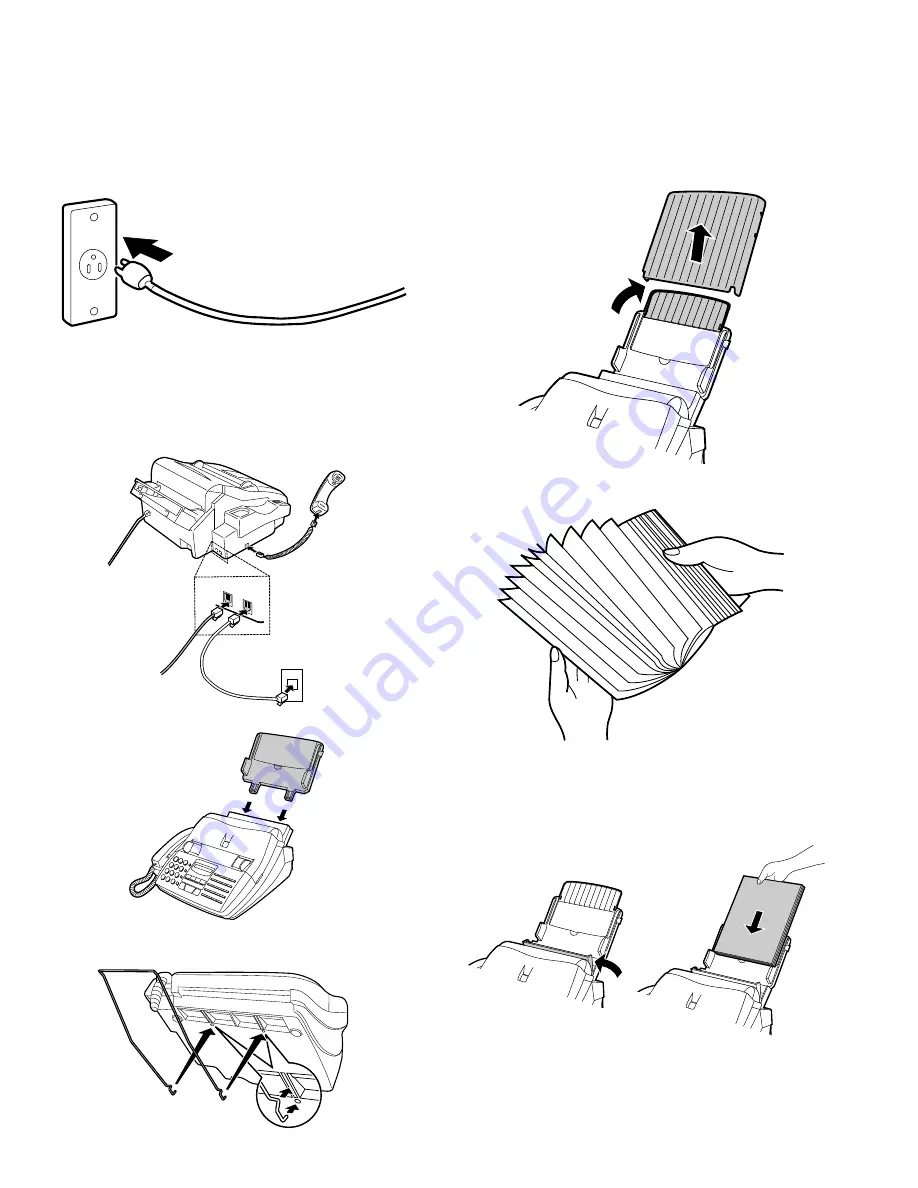
3. Assembly and connections
1
Plug the power cord into a 120 V, 60 Hz, grounded (3-prong)
outlet.
Caution: Do not plug the power cord into any other kind of outlet.
This will damage the machine and is not covered under
the warranty.
2
Connect the handset as shown and place it on the handset rest.
Insert one end of the telephone line cord into the "TEL. LINE"
jack. Insert the other end into a standard (RJ11C) single-line tele-
phone wall jack.
Be sure to insert the telephone line cord into the "TEL. LINE" jack.
Do not insert into the "TEL. SET" jack.
3
Insert the paper tray into the back of the fax as shown.
4
If desired, attach the original document support by inserting the
ends into the holes in the bottom of the fax as shown.
4. Loading printing paper
The paper tray holds the paper on which received documents and
copies are printed. Up to 200 sheets of letter or legal size paper from
16 to 24 lbs. (60 to 90 g/m
2
) can be loaded in the tray.
1
Remove the paper cover if it is on the paper tray.
•
If you are going to load legal size paper, flip up the paper tray
extender.
2
Fan the paper, and then tap the edge against a flat surface to
even the stack.
3
Pull the paper release plate toward you and insert the stack of
paper into the tray, print side down.
•
If paper remains in the tray, take it out and combine it into a single
stack with the new paper before adding the new paper.
AC outlet
TEL.
SET
TEL.
LINE
Handset
Wall jack
UX-510U/UX-510C/UX-500U
UX-500C/FO-1460U
1 – 6
Summary of Contents for FO-1460
Page 69: ...Control PWB parts layout Top side 6 7 UX 510U UX 510C UX 500U UX 500C FO 1460U ...
Page 70: ...Control PWB parts layout Bottom side 6 8 UX 510U UX 510C UX 500U UX 500C FO 1460U ...
Page 72: ...TEL LIU PWB parts layout 6 10 UX 510U UX 510C UX 500U UX 500C FO 1460U ...
Page 74: ...6 12 Power supply PWB parts layout UX 510U UX 510C UX 500U UX 500C FO 1460U ...
Page 77: ...Operation panel PWB parts layout 6 15 UX 510U UX 510C UX 500U UX 500C FO 1460U ...


