background image

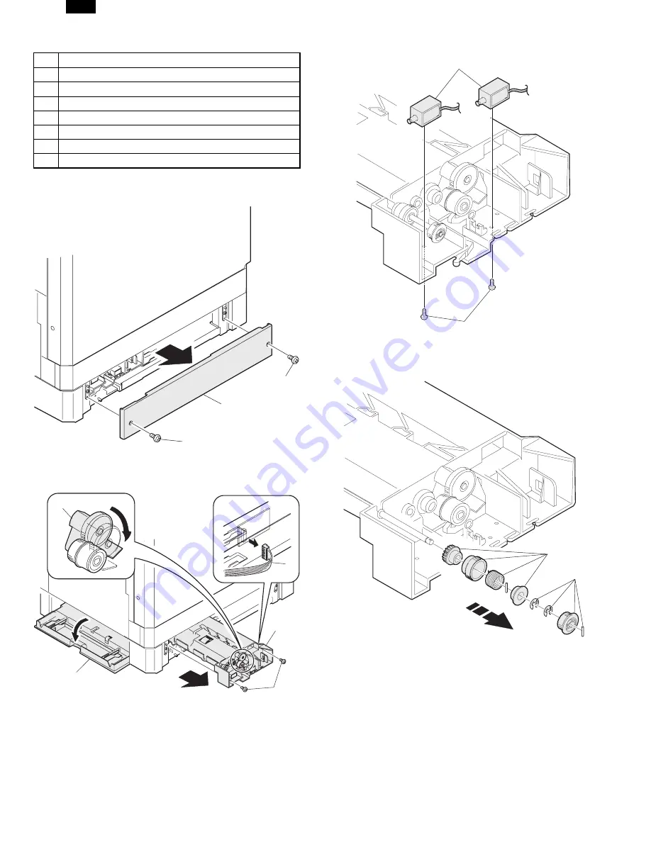
9. Second Tray section

No.

Content

A

Second Tray Rear Cover

B

Paper feed unit section

C

Paper feed solenoid, transport solenoid

D

Transport roller gear section

E

Transport roller

F

Paper feed roller clutch

G

Paper feed roller

A. Second Tray Rear Cover

B. Paper feed unit section

C.

Paper feed solenoid, transport solenoid

D. Transport roller gear section

1

1

2

2

3

5

4

1

1

2

1

2

DM-2000

11  – 10

Summary of Contents for DM-2000

Page 1: ... PROCEDURE 8 1 9 TROUBLE CODE LIST 9 1 10 USER SETUP 10 1 11 DISASSEMBLY AND ASSEMBLY 11 1 12 ELECTRICAL SECTION 12 1 CONTENTS Parts marked with are important for maintaining the safety of the set Be sure to replace these parts with specified ones for maintaining the safety and performance of the set SHARP CORPORATION This document has been published to be used for after sales service only The con...

Page 2: ...ÅPNES OG SIKKERHEDSLÅS BRYTES UNNGÅ EKSPONERING FOR STRÅLEN OSYNLIG LASERSTRÅLNING NÄR DENNA DEL ÄR ÖPPNAD OCH SPÄRRAR ÄR URKOPPLADE STRÅLEN ÄR FARLIG BETRAKTA EJ STRÅLEN AVATTAESSA JA SUOJALUKITUS OHITETTAESSA OLET ALTTIINA NÄKYMÄTÖNTÄ LASERSÄTEILYLLE ÄLÄ KATSO SÄTEESEEN Laserstrahl CLASS 1 LASER PRODUCT LASER KLASSE 1 Disconnect the AC cord before servicing the unit CLASS 1 LASER PRODUCT LASER K...

Page 3: ...allation 5 7 6 ADJUSTMENTS 6 1 1 Adjustment item list 6 1 2 Copier adjustment 6 1 7 SIMULATIONS 7 1 1 Entering the simulation mode 7 1 2 Cancelling the simulation mode 7 1 3 List of simulations 7 1 4 Contents of simulations 7 2 8 FLASH ROM VERSION UP PROCEDURE 8 1 1 MCU E SORT 8 1 2 Printer control PWB firmware version up 8 2 9 TROUBLE CODE LIST 9 1 1 Trouble code list 9 1 2 Details of trouble cod...

Page 4: ...ff the power switch disconnect the power plug then remove the dropped thing 8 Do not use a wet hand to disconnect or insert the power plug and to operate or service the machine It may cause an electric shock B CAUTION 1 Avoid installation on an unstable surface or a slant surface Other wise it may drop from the surface resulting in an injury It is ad visable to use the optional paper feed desk or ...

Page 5: ...pacity 250 2 Paper feed tray 100 Multi bypass tray 56 80 g m2 equivalent Remaining quantity detection Cassette section Empty detection available size detection by key input Multi bypass tray Only empty detection available 1 Paper feed section of the copier Paper feed size 11 17 8 5 14 8 5 13 8 5 11 8 5 11 R 8 5 5 5 8 5 5 5 is only for tray 1 Side front Front 2 step Paper feed capacity 250 sheets 5...

Page 6: ...ection from the document direction 2 in 1 4 in 1 Copies of 2 pages or 4 pages are integrated into one surface Divided by solid lines Selectable by the user program Edge erase Images surrounding the document are erased when copying Adjustable in 0 20 mm 5 mm step 0 1 1 4 step by the user program Center erase The image at the center is erased when copying Adjustable in 0 20 mm 5 mm step 0 1 1 4 step...

Page 7: ... 600 dpi 300 dpi 1 200 dpi equivalent by smoothing Toner save Available Paper feed tray Multi bypass tray Tray 1 Tray 2 Tray 3 Tray 4 Depends on the machine and the option installation Paper size Multi bypass tray A3 B4 A4R B5R A5 11 17 8 5 14 8 5 11 R 8 5 5 5 R 8 5 13 8 3 13 7 25 10 5 R DL C5 COM10 Tray 1 4 11 17 8 5 14 8 5 11 8 5 11 R 8 5 5 5 8 5 13 Paper exit Face down system Shifter Available ...

Page 8: ...stom Paper N Up Printing 1 Up 2 Up 4 Up Border On Off Fit to Page On Off Page Protection On Off Toner Save Mode On Off Item PCL6 PCL5e Smoothing On Off Resolution Settings 600 dpi 300 dpi Graphics Mode HP GL 2 Vector Raster Half Tone Photo Images Line Art Scanned Images Font Source Resident Fonts Download Fonts True Type Mode Download as True Type Download as bitmap font Print as graphics Input Tr...

Page 9: ...nnot make settings if the Data Remaining message is displayed Lit Indicates that the printer is on line and data can be transferred and printed DATA light Extinguished Indicates that there is no data being received or processed Lit Indicates that the printer is receiving or processing print data Blinking Indicates that there is print data remaining in memory that has not yet been printed c Operati...

Page 10: ... port A3 Short side B4 Short side A4 Long side A4R Short side B5 Long side B5R Short side A5 Long side A5R Short side Ledger Short side Legal Short side Letter Long side LetterR Short side Invoice Long side InvoiceR Short side Foolscap Short side Folio Short side Executive Short side COM 10 Short side C5 Short side DL Short side For paper feed of the multi bypass tray the short side must be set to...

Page 11: ...7560 120 100 300 7600 0 Executive 6300 4350 6060 120 100 300 6100 0 COM 10 5700 2474 3460 120 100 300 5500 0 C5 5408 3826 5172 118 100 300 5208 0 DL 5196 2598 4960 118 100 300 4996 0 Unit Dots 600DPI Top Margin The set value is received from the digital copier and data are made ac cording to the set value Left margin Since the paper size sensor is not set the digital copier does not know the size ...

Page 12: ...ier Italic SWC 41 Fixed Pitch 810 Courier Bold Italic SWC 42 Fixed Pitch 850 Letter Gothic 12 pitch text SWC 43 Fixed Pitch 850 Letter Gothic Bold 12 pitch text SWC 44 Fixed Pitch 850 Letter Gothic Italic 12 pitch text SWC 45 Line Printer b For PS2 Font Name Dutch 801 SWA DutchTM 801 Bold SWA Dutch 801 Italic SWA Dutch 801 Bold Italic SWA SwissTM 721 SWA Swiss 721 Bold SWA Swiss 721 Oblique SWA Sw...

Page 13: ...uct name Package Remark 1 Developer cartridge Black Toner developer cartridge Toner 610 g Developer 395 g 1 15K DM 200TD 4 Life setting by A4 6 documents Returned Operation Manual 1 Vinyl bag TINSZ0031YSZZ 1 2 Drum cartridge Drum cartridge 1 30K DM 200DR 4 Note Maintenance parts other than mentioned above must be ordered through the parts department using the proper part number 2 Environment condi...

Page 14: ...um cartridge shows the date of production Division No Ex production 1 Option 2 Same pack 3 The end digit of production year January September October November December 1 9 0 X Y Indicates production in China Destination Serial number 00001 99999 Production month B 1 The end digit of production year January September October November December 1 9 0 X Y Factory Serial number for each month 00001 999...

Page 15: ...r 9 Paper trays 10 Side cover 11 Side cover handle 12 Bypass tray guides 13 Bypass tray 14 Bypass tray extension 15 Charger cleaner 2 Internal 1 Drum cartridge handle 2 Drum cartridge 3 TD cartridge lock release lever 4 TD cartridge strap 5 TD cartridge 6 Roller rotating knob 7 Fusing unit release levers 8 Paper guide 1 2 3 4 5 6 7 8 9 3 10 11 12 13 14 15 6 8 7 1 2 3 4 5 DM 2000 4 1 ...

Page 16: ...ode is com pleted and that the fusing temperature is in ready state The combinations of the above display lamps are as follows ON OFF Lamp Immediately after power ON Ready Copying Pre heat lamp Blink Ready lamp Other lamps Lamp Energy saving mode Pre heating Energy saving mode Auto power shut off Resetting from energy saving mode Copy is started during resetting from energy saving mode Pre heat la...

Page 17: ...oid MPFS Manual paper feed solenoid 11 Manual paper transport clutch MPTC Drives the manual paper transport roller 12 Second tray transport clutch CPFC2 Drives the second tray transport roller 13 Second tray transport solenoid FSOL2 Second tray transport solenoid 14 First tray transport solenoid FSOL1 First tray transport solenoid 15 Second tray paper feed solenoid PSOL2 Second tray transport sole...

Page 18: ...t detection 11 Shifter home position sensor SFTHP Shifter home position detection 12 Thermistor RTH Fusing section temperature detection 13 Thermostat Fusing section abnormally high temperature detection 14 1st tray detection switch CSD1 1st tray detection 15 Paper in PIN Paper transport detection 16 2nd tray detection switch CSD2 2nd tray detection 17 Manual sensor MPED Manual transport detection...

Page 19: ...ontrol 5 Network Board Network system interface 6 CCD sensor PWB Image scanning 7 Motor PWB 8 Main PWB MCU Machine control Image process 9 Paper exit interface PWB Paepr exit finishing control 10 Tray interface PWB Paper tray control 11 Operation main PWB Operation panel input Display operation panel section control 12 LCD PWB Printer and FAX status display 1 2 3 4 9 6 5 10 7 8 12 11 DM 2000 4 5 ...

Page 20: ...ports waste toner to the waste toner box 11 Drum unit Forms images 12 Transfer charger unit Transfer images on the drum onto paper 13 Resist roller Takes synchronization between the paper lead edge and the image lead edge 14 Manual paper feed tray Manual paper feed tray 15 Manual paper feed roller Picks up paper in manual paper feed 16 Manual transport roller Transports paper from the manual paper...

Page 21: ...nd a leakage occurs a fire or an electric shock may be result 2 Removal of protective material and fixing screw 1 Remove all tapes and protective material Remove all tapes then open the document cover and remove the protective material of sheet shape 2 Remove the fixing screw Use a coin to remove the fixing screw The fixing screw is required when transporting the machine Keep it in the tray Refer ...

Page 22: ... Store the fixing screw which was removed in the above proce dure 2 and the fixing screw which was removed in procedure 2 of 2 Removal of protective material and fixing screw in the storage place in the tray 5 Changing the copy paper size in the tray 1 Gently lift and pull out the paper tray until it stops 2 Push the pressure plate down until it locks in place 3 Squeeze the lock lever of the front...

Page 23: ...he on screen instructions Before installation make sure that You read the README TXT file which is contained on the SHARP Software CD ROM This file contains the information and restrictions for using the printer The printer is connected properly with the computer or network The printer is loaded with paper The printer is turned on and on line the ON LINE light is lit You quit all application softw...

Page 24: ...e Plug Play Function 5 Set the printer name 1 If you want to change the printer name enter a new name in the space provided 2 If the program displays Do you want your Windows based programs to use this printer as the default printer check Yes 3 Click the Next button 6 Print a test page by clicking the Finish button Note If you check No and click the Finish button the printer does not print a test ...

Page 25: ...or if you want to use this printer as a network printer follow the procedure in this section The following steps use Windows 98 in display examples 1 Turn the computer on and start Windows 95 98 2 Click the Start menu point to Settings and choose Printers 3 When the Printers window appears double click the Add Printer icon 4 Click the Next button 5 If the screen for choosing the connection method ...

Page 26: ...ck the Start menu point to Settings and choose Printers 3 When the Printers window appears double click the Add Printer icon 4 Choose My Computer or Network printer server and click the Next button The following steps use My Computer as an example For more information about using this printer as a network printer refer to the Windows NT 4 0 networking documentation 5 Check the checkbox for the por...

Page 27: ...iguration Settings After installing the printer driver use the procedure in this section to change the printer configuration settings Also refer to the print driver help for more information 1 Click the Start menu point to Settings and choose Printers 2 Right click the appropriate printer and choose Properties from the menu 3 Click the Configuration tab and change the printer settings 7 Expansion ...

Page 28: ... 2 Copier adjustment A Process section 1 Developing bias voltage adjustment Note Use a digital multi meter with an internal resistance of 10 MΩ or more 1 Set the digital multi meter range to DC700V 2 Put the test rod of the digital multi meter on the developing bias voltage output check pin 3 Turn on the power 4 Adjust the adjustment volume VR31 so that the output voltage is within the specified r...

Page 29: ...ad edge position Exposure display AUTO ON again 1 step of the set value corresponds to about 0 127 mm shift Calculate the set value from the formula below 99 R 0 127 mm Image loss set value R Image loss meas urement value mm Example 99 4 0 127 99 31 5 about 67 Note If the set value is not obtained from the above formula per form the fine adjustment 9 Measure the distance H between the paper lead e...

Page 30: ...11 Paper rear edge Scale image Paper rear edge Void amount Standard value 4mm or less 4 Execute SIM 50 1 5 Set the SPF lead edge position set value Exposure display MANUAL ON so that the same image is obtained as that ob tained in the previous OC image lead edge position adjustment Adjustment specification Adjustment mode SIM LED Set value Spec value Set range SPF image lead edge position 50 1 MAN...

Page 31: ...e following adjustment procedure The first copy does not show the void Be sure to check the second copy 3 Execute SIM 50 1 and set the density mode to AUTO MANUAL Left edge void The currently set adjustment value is displayed When the off center adjustment previously described is per formed 0 is displayed 4 Enter the set value and press the start key The correction value is stored and a copy is ma...

Page 32: ...e as shown below 2 Open the original cover and make a normal 100 copy 3 Measure the width of the black background at the lead edge and at the rear edge If the width La of the black background at the lead edge is equal that Lb at the rear edge there is no need to execute the follow ing procedures of 4 7 4 Loosen the mirror base drive pulley fixing screw on the front frame side or on the rear frame ...

Page 33: ... direction to adjust When La Lb Shift the mirror base B rail upward by the half of the difference of La Lb When La Lb Shift the mirror base B rail downward by the half of the difference of Lb La Example When La 12 mm and Lb 9 mm shift the mirror base B rail upward by 1 5 mm When Lc Ld Shift the mirror base B rail downward by the half of the difference of Lc Ld When Lc Ld Shift the mirror base B ra...

Page 34: ...he display section in 2 digits 5 Enter the set value and press the start key The set value is stored and a copy is made Adjustment specification Mode Specification SIM Set value Set range Sub scanning direction magnification ratio OC mode Normal 1 0 SIM 48 2 Add 1 0 1 increase Reduce 1 0 1 decrease 1 99 b SPF mode in copying Note Before performing this adjustment be sure to check that the CCD unit...

Page 35: ...302mm 4 If the OC SPF open close position A is not 207 302mm adjust the open close sensor mounting plate position as shown below 9 Original sensor adjustment SIM 43 3 1 Execute SIM 41 2 2 Set A3 11 17 paper on the OC table 3 Press the start key again 4 The sensor level of the original sensor is automatically checked and the value with an original 40 is made as the threshold value for scanning Auto...

Page 36: ...oping preset counter value display Japan only A 8 SPF counter display A 9 Paper feed counter display 12 Drum counter display 14 Copier ROM version display Main code Sub code Contents 22 15 Trouble memory display 16 Duplex print counter display A 17 Copy counter display 18 Printer counter display 19 Electronic sort counter display C 20 FAX print counter display D 21 Scanner counter display 24 1 JAM...

Page 37: ...e RSPF reverse solenoid RSOL at the cycle of 500 msec ON and 500 msec OFF 20 times 10 RSPF paper exit gate solenoid operation check Not used Used to drive the RSPF paper exit gate solenoid GSOL at the cycle of 500 msec ON and 500 msec OFF 20 times 11 SPF PS release solenoid operation check SPF is required Used to drive the SPF PS release solenoid at the cycle of 500 msec ON and 500 msec OFF 20 tim...

Page 38: ...the copier side cover open then close the side cover and the machine will start warming up Warm up time is counted up every second and it is displayed After completion of warmup count up is terminated When the clear all key is pressed ready lamp is lighted and the copy quantity is entered and the start key is pressed copying is made to make the set quantity of copies At that time the paper size do...

Page 39: ...ed and the start key is pressed the set value is stored 50 18 76 10 Toner motor operation check Used to operate the toner motor for 30 sec Note If this simulation is executed with the toner hopper installed toner is automatically supplied to the developer Be careful of overtoning 14 Trouble except for U2 cancel Used to cancel troubles except for U2 16 U2 trouble cancel Used to cancel U2 trouble 20...

Page 40: ...he operation panel When the start key is pressed during the main code display the sub code is displayed Max 20 recent trouble codes are stored 16 Duplex print counter display Not used Used to display the current duplex print counter value 1 17 Copy counter display Used to display the current copy counter value 1 18 Printer counter display Used to display the current printer counter value 1 19 Elec...

Page 41: ...es at a low speed 10 Polygon motor operation check Used to drive the polygon motor for 30 sec 26 1 Option switch display Used to display the installed option on the operation panel The LED corresponding to the installed option is lighted 3 Auditor setting Used to display the current auditor setting with the numbers at right After entering the set value press the start key and the set value is stor...

Page 42: ...ng Used to display the current setting of CE mark conformity control with the number at right After entering the set value press the start key and the set value is stored 0 0 1 Key operation Display 0 Total Developer 2 counts Maintenance 2 counts 1 Total Developer 1 count Maintenance 2 counts 2 Total Developer 2 counts Maintenance 1 count 3 Total Developer 1 count Maintenance 1 count Key operation...

Page 43: ...ayed with the following numbers After entering the set value press the start key to store the set value 1 0 1 30 1 Machine sensor operation check Used to check the sensors in the machine transport system with LED on the operation panel 41 2 OC document sensor adjustment Used to read the document sensor input value with paper and perform the sensor detection level adjustment For the adjustment proc...

Page 44: ... adjustment in copying After completion of warmup shading is performed and the currently set OC mode sub scanning direction magnification ratio adjustment in copying is performed For the adjustment procedure refer to the previous descriptions 50 1 99 2 Display after clearing each counter 000 0 75 sec Blank 0 35 sec 000 0 75 sec Blank 1 0 sec Repetition Key operation Display Light reception Detecti...

Page 45: ...1 99 10 Paper off center adjustment After completion of warmup shading is performed and the currently set off center adjustment of each paper feed port is displayed For the adjustment procedure refer to the previous descriptions 50 1 99 Key operation Display Adjustment mode select Exposure mode select key Auto SPF mode sub scanning direction magnification ratio in copying Set value Copy quantity k...

Page 46: ... set resist amount adjustment value is displayed 50 1 for the second cassette only 1 99 63 1 Shading data check The copy lamp is shifted to the shading position and it is lighted with the reference voltage at AD conversion fixed Vref 0 5V Vref 4 5V The level of one pixel at the center at that time is displayed 64 1 Self print mode Disregards the optical system and performs self printing in 1 by 2 ...

Page 47: ...p at the rear of the machine 4 Connect the serial connector 5 Turn on the power of the machine The machine enters the download mode All LED lamps are turned off The machine accepts no key operations 6 Execute mainte Vxxx exe on the PC Use mainte_vxxx exe ver 1 04 or later 7 Communication port communication speed setting Select Comport in the option menu and select the most suitable item with consi...

Page 48: ...onfiguration Page ENTER The test page prints 2 Connect the PC and the copier with the parallel cable 3 Turn on the power 4 Execute SIM 67 14 Erase Flash Data is displayed on the LCD 5 Press the ENTER key on the copier s operation panel Now Erasing is displayed on the LCD 6 After deletion of data Please Send Data is displayed on the LCD and the machine enters the ready state for data input 7 Downlo...

Page 49: ... trouble 80 Printer PWB communication trouble Protocol 81 Printer PWB communication trouble Parity 82 Printer PWB communication trouble Overrun 84 Printer PWB communication trouble Framing 88 Printer PWB communication trouble Time out H2 00 Thermistor open detection H3 00 Heat roller abnormally high temperature H4 00 Heat roller abnormally low temperature L1 00 Mirror base feed trouble L3 00 Mirro...

Page 50: ...lash ROM abnormality is detected in the E Sort PWB Control circuit hung up due to noises Flash ROM peripheral circuit error E1 13 Check and remedy Replace the E Sort PWB Rewrite the flash ROM data Check grounding of the machine 14 Content E Sort PWB Work RAM error Detail E Sort PWB Work RAM abnormality Cause A Work RAM abnormality is detected in the E Sort PWB Control circuit hung up due to noises...

Page 51: ... Sort PWB communication trouble Time out Detail Communication trouble between MCU and E Sort PWB Time out error Cause E Sort PWB connector disconnection E Sort PWB MCU PWB harness failure E Sort Motherboard connector pin breakage E Sort PWB ROM defect data failure Check and remedy Check the connectors and harness of the E Sort PWB and the MCU PWB Check grounding of the machine Check the ROM of the...

Page 52: ...oes not light Check for heater lamp disconnection or thermostat disconnection Check the interlock switch Check the power PWB and MCU PWB lamp control circuit Clear the trouble with SIM 14 L1 00 Content Mirror base feed trouble Detail The mirror home position MHPS does not turn off though the feed operation is completed during mirror initial operation after turning on the power The mirror home posi...

Page 53: ...lure U2 12 Check and remedy Check that the EEPROM is properly set To prevent against loss of counter adjustment values record the values with simulation U2 trouble cancel with SIM 16 MCU PWB replacement U3 29 Content Mirror base home position error Detail Home position is not detected when starting mirror base shift Cause Mirror unit defect Mirror home position sensor defect MCU PWB defect Scanner...

Page 54: ...ontrol PWB connector Defective harness between FAX control PWB and MCU PWB Motherboard connector pin breakage FAX control PWB ROM error Data error F6 10 Check and remedy Check connector harness between FAX control PWB and MCU PWB Check grounding of the machine Check FAX control PWB ROM 80 Content FAX control PWB communication trouble Protocol Detail Communication trouble between MCU and FAX contro...

Page 55: ... protocol error Cause Bad connection of printer PWB connector Defective harness between printer PWB and MCU PWB Motherboard connector pin breakage Printer PWB ROM error data error Check and remedy Check connector harness of printer PWB and MCU PWB Check grounding of the machine Check printer PWB ROM 10 Content Printer PWB trouble Detail Communication trouble between MCU and printer PWB Cause Bad c...

Page 56: ...nter erase areas 17 Layout in 2 in 1 copy Selects a pattern for 2 in 1 copying 18 Layout in 4 in 1 copy Selects a pattern for 4 in 1 copying 19 Offset of paper output tray Enables or disables the offset function of the paper output tray The offset function can be specified respectively for the upper and lower areas separated by an optional job separator tray kit These programs do not affect the co...

Page 57: ... Account number entry Program No 11 is used to register accounts When program No 11 is entered 1 Enter a 3 digit account number using the numeric keys Any 3 digit number except 000 can be registered as an ac count number 2 Press the START key If a number that is already registered or 000 is entered the number will blink in the copy quantity display 3 Repeat steps 1 and 2 for other account numbers ...

Page 58: ...t again from 0 3 Repeat steps 1 and 2 for other account numbers 4 To continue with other user programs press the clear key and select another program number To exit the user program mode press the light key F Program No 15 Resetting account If no account number has been registered 15E will appear in the copy quantity display Press the clear key The DM Sytem will return to step 2 1 To reset an indi...

Page 59: ...Test Printing Menu Configuration Page PCL Font List PS2 Font List Item Item Item Basic Menu Setting Procedure Note The menus and items displayed may be different depending on the optional functions installed 1 When the printer is not in use press the ON LINE key to put the printer off line 2 Press the MENU key repeatedly until the required menu appears 3 Press the ITEM key repeatedly until the req...

Page 60: ...per tray loaded with the paper of the size specified in the Paper Size item The available settings reflect the installed trays Item Possible Settings Description Paper Size A3 B4 A4 B5 A5 Ledger Legal Letter Executive Folio Invoice Foolscap COM 10 DL C5 Sets the size of the paper where data will be printed If this size is different from the paper size present in the tray the size set on the operat...

Page 61: ...onfiguration Page HARDWARE STATUS KEY MENU STATUS Machine Information Language Hardware Specs Base Memory Total Memory Network Board Version Information PCL6 Input Paper Trays Bypass Tray Tray 1 Tray 2 Tray 3 Tray 4 Main Menu Copies Resolution Smoothing Toner Save Paper Source Paper Size Orientation Emulation 1 600dpi On Off Auto Letter 8 5x11 Portrait PCL Interface Menu I O Time Out 60 sec Englis...

Page 62: ...ed Legal 8 1 2 14 Legal Short Edge Feed Ledger 11 17 Ledger Short Edge Feed Executive 7 1 4 10 1 2 Executive Short Edge Feed Invoice 5 1 2 8 1 2 Invoice Long Edge Feed Foolscap 8 1 2 13 Foolscap Short Edge Feed A4 A4 Long Edge Feed A4R A4 Short Edge Feed B5 B5 Long Edge Feed B5R B5 Short Edge Feed B4 B4 Short Edge Feed A3 A3 Short Edge Feed A5 A5 Long Edge Feed A6 A6 Short Edge Feed Unknown Other ...

Page 63: ...n Paper transport section 9 Second Tray section 10 Manual multi paper feed section 11 Power section 1 High voltage section No Content A Transfer charger unit B Charger wire A Transfer charger unit B Charger wire Installation The spring tip must be between two reference ribs The charger wire must be free from twist or bending Be sure to put the charger wire in the V groove 2 Optical section No Cont...

Page 64: ...s unit so that the lens unit number on the lens ad justment plate is aligned with the scribe line on the base plate Example Lens unit number 2 8 Attach the lens unit at 2 scales in the paper exit direc tion from the reference line Note Never touch the other screws than the unit attachment screw The lens unit is supplied only in a whole unit 3 Fusing section No Contents A Fusing unit B Thermostat C...

Page 65: ... Assembly Put the paper guide earth spring A under the paper guide B before fusing Disassembly There are three pawls on the fusing cover Remove the screws and slide the fusing cover to the right to remove The heater lamp is fixed on the fusing cover with a screw Slide the fusing cover to the front and remove the screw then remove the heater lamp 2 3 1 1 2 3 1 1 2 1 A B 2 1 2 3 4 3 B A DM 2000 11 3...

Page 66: ... E Upper heat roller F Upper heat roller separation pawl G Lower heat roller Assembly When installing the paper guide 3 before fusing tighten the paper guide fixing plate so that the paper guide fixing plate 2 is in contact with the frame bottom section A under fusing 6 5 8 9 7 8 1 0 A B C 2 1 4 3 3 2 1 2 2 1 1 3 3 1 4 1 2 3 2 A DM 2000 11 4 ...

Page 67: ...pawls 4 Paper exit section No Content A Front cabinet unit Right cabinet unit B Paper exit unit C Transport roller D Paper exit roller A Front cabinet unit right cabinet B Paper exit unit removal C Transport roller 3 2 1 1 6 6 5 4 5 5 1 2 5 B A 3 4 4 7 6 8 6 8 1 0 9 9 1 2 1 DM 2000 11 5 ...

Page 68: ... faces in the longitudinal direction of the paper exit drive gear long hole B Be sure to insert two ribs C into the groove D 5 MCU Mother board Printer control PWB No Content A Mother board B MCU C Printer control PWB A Mother board 3 4 6 7 5 5 1 3 2 2 4 4 5 B A D C C 8 6 6 7 7 1 DM 2000 11 6 ...

Page 69: ...to the attached Flash ROM version up proce dures No XXX C Printer control PWB Note When replacing the printer control PWB check that the firmware is of the latest version If the firmware is not of the latest version perform the version up procedures described later 6 Optical frame unit No Content A Optical frame unit A Optical frame unit Installation Install the optical unit in the sequence shown ...

Page 70: ...Tray paper feed section Paper transport section No Content A Interface frame unit B Drive unit C Solenoid paper feed solenoid resist roller solenoid D Resist roller clutch Resist roller E Paper feed clutch Paper feed roller Semi circular roller A Intermittent frame unit Assembly Do not miss the door lock pawl 1 2 1 1 3 4 6 5 5 1 1 2 2 4 3 DM 2000 11 8 ...

Page 71: ...awl as shown below and avoid the clutch and install C Solenoid paper feed solenoid resist roller solenoid D Resist roller clutch Resist roller E Paper feed clutch Paper feed roller Semi circular roller 1 2 1 2 2 3 1 4 3 2 3 3 4 1 3 2 DM 2000 11 9 ...

Page 72: ... feed solenoid transport solenoid D Transport roller gear section E Transport roller F Paper feed roller clutch G Paper feed roller A Second Tray Rear Cover B Paper feed unit section C Paper feed solenoid transport solenoid D Transport roller gear section 1 1 2 2 3 5 4 1 1 2 1 2 DM 2000 11 10 ...

Page 73: ... roller NOTE Engage connection arm spring B with frame groove A and con nection arm groove C 10 Manual multi paper feed section No Content A Manual multi paper feed section B Manual transport clutch C Manual paper feed clutch D Manual transport roller Manual paper feed roller E Multi feed solenoid A Manual multi paper feed 1 1 2 A B 3 A 1 2 1 1 2 B A C 2 1 2 3 A DM 2000 11 11 ...

Page 74: ... arm 1 then remove it Assembly Install so that the boss section of the fulcrum arm 2 comes between ribs Disassembly Set up the cam transmission arm 2 and remove it Assembly Install so that the cam transmission arm 2 is under the roller arm A 5 1 1 2 3 4 1 2 4 3 A 7 5 6 8 DM 2000 11 12 ...

Page 75: ...reful of the installing direction of the manual transport roller 4 E Multi feed solenoid Assembly Install so that the latches A and B move smoothly 11 Power section No Content A Power unit A Power unit L C K T O K O 2 3 1 4 5 2 1 2 A B 3 4 5 3 3 4 2 1 1 1 1 DM 2000 11 13 ...

Page 76: ... 12 ELECTRICAL SECTION 1 Block diagram DM 2000 12 1 ...

Page 77: ...2 Actual wiring diagram Actual wiring diagram 1 3 DM 2000 12 2 ...

Page 78: ...Actual wiring diagram 2 3 DM 2000 12 3 ...

Page 79: ...Actual wiring diagram 3 3 DM 2000 12 4 ...

Page 80: ...edgments Windows and Windows NT are trademarks of Microsoft Corporation in the U S A and other countries IBM and PC AT are trademarks of International Business Machines Corporation PCL is a trademark of Hewlett Packard Company Pentium is a registered trademark of Intel Corporation All other trademarks and copyrights are the property of their respective owners SHARP CORPORATION Digital Document Sys...

Reviews: