Sharp AL-2051 Service Manual Download Page 82

AL-2051  SIMULATION, TROUBLE CODES  10 - 6
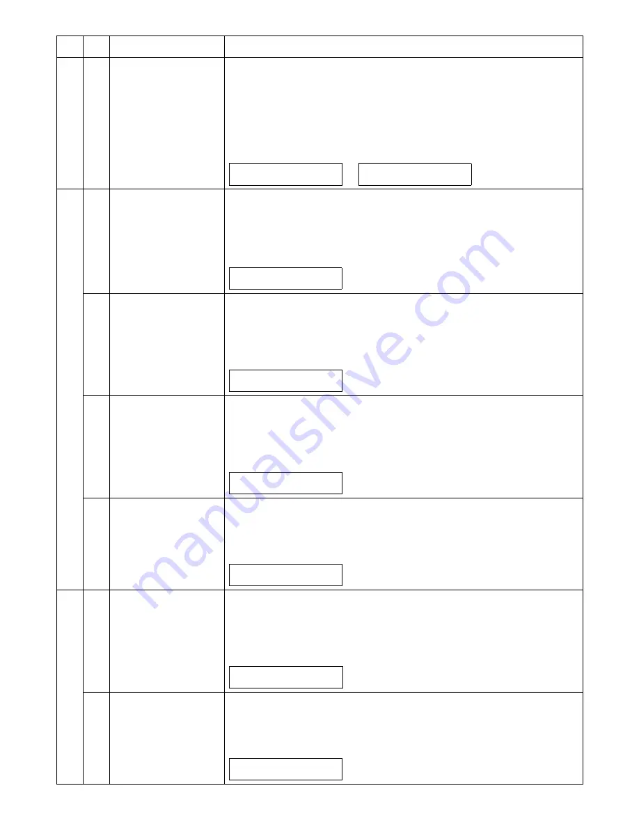
7

08

Shift to copy with the 
warm-up display

[Function]

Enter the simulation code, and warm-up is started and warm-up time is counted for every sec-
ond from 0 and displayed.
When [Clear All] key is pressed during counting up, "0" is displayed on the display and counting
is stopped. However, warm-up is continued.
After completion of warm-up, counting is terminated. (The aging function is removed from simu-
lation 7-01.)

[Operation]

8

01

Developing bias

[Function]

When [ENTER]/[START] key is pressed, the developing bias signal is turned ON for 30sec.

When, however, an actual output value is measured, use simulation 25-01.

After completion of this process, the machine goes into the sub code entry standby mode.

[Operation]

02

Main charger (Grid high)

[Function]

When [ENTER]/[START] key is pressed, the main charger is outputted for 30sec in the grid volt-
age HIGH move.

After completion of this process, the machine goes into the sub code entry standby mode. 

[Operation]

03

Grid voltage (Low)

[Function]

When [ENTER]/[START] key is pressed, the main charger is outputted for 30sec in the grid volt-
age LOW move.

After completion of this process, the machine goes into the sub code entry standby mode.

[Operation]

06

Transfer charger

[Function]

When [ENTER]/[START] key is pressed, the transfer charger is outputted for 30sec.

After completion of this process, the machine goes into the sub code entry standby mode.

[Operation]

9

01

Duplex motor normal 
rotation operation check

[Function]

Use the duplex motor Bios to drive the duplex motor in the normal direction (paper exit direc-
tion) for 30sec.

After completion of this process, the machine goes into the sub code entry standby mode.

[Operation]

02

Duplex motor reverse 
operation check

[Function]

Use the duplex motor Bios to drive the duplex motor in the reverse direction for 30sec.

After completion of this process, the machine goes into the sub code entry standby mode.

[Operation]

Main 
code

Sub 

code

Contents

Details of function/operation

1) Initial display

2) After 10sec

0

7-

0

8 W-U

P


C

-M

ODE


0

0

7-

0

8 W-U

P


C

-M

ODE


10

1) Initial display

0

8-

01


D

VL

P

 BI

A

S S

ET.

E

X

EC

U

T

ING

...

1) Initial display

0

8-

0

2 MHV(H) S

ET.

E

X

EC

U

T

ING

...

1) Initial display

0

8-

0

3 MHV(L) S

ET.

E

X

EC

U

T

ING

...

1) Initial display

0

8-

0

T

HV S

ET.

E

X

EC

U

T

ING

...

1) Initial display

0

9-

01


DP

LX 

ROT.

E

X

EC

U

T

ING

...

1) Initial display

0

9-

0

DP

LX 

ROT.RE

V

.

E

X

EC

U

T

ING

...

Summary of Contents for AL-2051

Page 1: ...t to change without notice SERVICE MANUAL CONTENTS SHARP CORPORATION CODE 00ZAL2051 S1E DIGITAL MULTIFUNC TIONAL SYSTEM MODEL AL 2051 1 GENERAL 1 1 2 SPECIFICATIONS 2 1 3 CONSUMABLE PARTS 3 1 4 EXTERNAL VIEWS AND INTERNAL STRUCTURES 4 1 5 UNPACKING AND INSTALLATION 5 1 6 COPY PROCESS 6 1 7 OPERATIONAL DESCRIPTIONS 7 1 8 DISASSEMBLY AND ASSEMBLY 8 1 9 ADJUSTMENTS 9 1 10 SIMULATION TROUBLE CODES 10 ...

Page 2: ... inserting wedges or other items into the switch slot LASER WAVE LENGTH 770 795nm Pulse times 10 24μsec Out put power 0 15mW 0 01mW CAUTION INVISIBLE LASER RADIATION WHEN OPEN AND INTERLOCKS DEFEATED AVOID EXPOSURE TO BEAM VORSICHT UNSICHTBARE LASERSTRAHLUNG WENN ABDECKUNG GEÖFFNET UND SICHERHEITSVERRIEGELUNG ÜBERBRÜCKT NICHT DEM STRAHL AUSSETZEN VARO AVATTAESSA JA SUOJALUKITUS OHITETTAESSA OLET A...

Page 3: ...KLASS 1 LASER APPARAT At the production line the output power of the scanner unit is adjusted to 0 57 MILLI WATT PLUS 20 PCTS and is maintained constant by the operation of the Automatic Power Control APC Even if the APC circuit fails in operation for some reason the maximum output power will only be 15 MILLI WATT 0 1 MICRO SEC Giving and accessible emission level of 42 MICRO WATT which is still l...

Page 4: ... DESCRIPTIONS 1 Outline of operation 7 1 2 Scanner section 7 2 A Scanner unit 7 2 B Optical system 7 2 C Drive system 7 2 3 Laser unit 7 3 A Basic structure 7 3 B Laser beam path 7 3 C Composition 7 3 4 Fuser section 7 3 A General description 7 4 5 Paper feed section and paper transport section 7 4 A Paper transport path and general operations 7 4 6 Process unit new drum detection mechanism 7 7 7 ...

Page 5: ...sity adjustment 9 4 C Necessary tool for copy density adjustment 9 4 D Features of copy density adjustment 9 4 E Copy density adjustment procedure 9 5 3 High voltage adjustment 9 5 A Main charger Grid bias 9 5 B DV bias check 9 6 4 Duplex adjustment 9 6 A Adjusting the paper reverse position in memory for duplex copying 9 6 B Adjusting trailing edge void in duplex copy mode 9 6 5 RSPF scan positio...

Page 6: ...ter function with USB SPLC printer SPLC printer function E SORT Electronic sort function Duplex Auto duplex copy print function Shifter Job separator function Scan to USB Scan to USB FAX FAX function Sharpdesk Scanner utilities USB Interface port USB Network Network 10 100 Base Descriptions of table Standard provision No function or no option available Opt Option Item Model CPM A4 PPM A4 SB MB 2 T...

Page 7: ...ard paper specified paper recycled paper Remark User adjustment of paper guide available Multi bypass paper feed section Paper size Max feedable size 8 1 2 x 14 Min feedable size 3 87 x 5 83 Paper weight 15 34 5 lbs Paper feed capacity 50 sheets 80g m2 Kinds Standard paper specified paper recycled paper OHP Label Envelop Single copy Remark User adjustment of paper guide available Paper exit sectio...

Page 8: ...0Wh H or less Average stand by 80Wh H or less Pre heat mode 28Wh H or less Section item Details Copy ratio Document glass Variable 25 to 400 in 1 increments total 376 steps Fixed 50 70 86 100 141 200 50 64 78 100 129 200 RSPF Variable 50 to 200 in 1 increments total 151 steps Fixed 50 70 86 100 141 200 50 64 78 100 129 200 Manual steps Text Photo 5 steps Copy speed CPM First copy time 1 Approximat...

Page 9: ...stScript 3 3 Installed fonts PCL6 compatible 80 outline fonts and 1 bitmap font PostScript 3 compatible 3 136 outline fonts Interface 10Base T 100Base TX Ethernet Type Flat Bed Color Scanner Scanning system Original table RSPF Light source 3 CCDs RGB sensor scanning by lighting white lamp 1 pcs of CCFL Resolution Optical 600 x 600dpi Setting range 50 9600dpi Preview resolution is fixed at 75dpi Or...

Page 10: ...ument AL 100DR 5 No Name Content Life Product name Package 1 Develop cartridge Black 6K Toner developer cartridge x 1 IC Chip Yes Stirring function Yes 6K A4 5 document AL 204TD 5 2 Develop cartridge Black 4K Toner developer cartridge x 1 IC Chip Yes Stirring function Yes 4K A4 5 document AL 214TD 5 3 Drum cartridge Drum cartridge x 1 18K AL 100DR 5 No Name Content Life Product name Package 1 Deve...

Page 11: ... on the drum cartridge shows the date of production SOCC production 1 The production control label is not attached to the cartridge of a China product Humidity RH 85 60 20 10 C 30 C 35 C Humidity RH 90 60 15 25 C 30 C 40 C Humidity RH 90 20 5 C 45 C Model name Color code Destination Skating Production place Production date YYYYMMDD Serial number Version number Production month Production day Desti...

Page 12: ...ray extension 9 Paper output tray 10 Paper output tray extension 11 Power switch 12 Handles 13 Power cord socket 14 Paper holder arm 1 Front cover 2 Side cover 3 Fusing unit release lever 4 Transfer charger 5 Charger cleaner 2 3 4 1 5 6 7 8 9 10 11 14 12 12 13 RSPF Exit area Bypass tray Original guides Document feeder tray Document feeder cover Interface USB connector Device USB connector Host LAN...

Page 13: ... to select the paper size for copying to configure a user program or to display the total count 11 2 SIDED COPY key Use to copy both sides of an original 12 E SORT SP FUN key Press to select the sort function 2 IN 1 copy function or margin shift function 13 key key OK key Press the key or key to select an item in a function setting menu Press the OK key to enter a selection 14 EXPOSURE key Use to ...

Page 14: ...an motor VFM Ventilate the fuser section 5 Resist roller solenoid RRS Resist roller rotation control solenoid 6 Paper feed solenoid CPFS1 Cassette Paper feed solenoid 1 7 Multi paper feed solenoid MPFS Multi manual pages feed solenoid 8 Drive motor SPMT Drives the RSPF 9 Duplex motor DMT Devices the duplex paper transport section 10 Shifter motor SFTM Drives the shifter 11 Reverse clutch SRVC Reve...

Page 15: ...nstallation detection H at cassette insertion 5 PPD1 sensor PPD1 Transmission sensor Paper transport detection 1 L at paper pass 6 Door switch DSW Micro switch Door open close detection safety switch for 24V 1 or 0V of 24V at door open 7 Drum reset switch DRST Micro switch New drum detection switch Instantaneously H at insertion of new drum 8 Paper empty sensor SPID Transmission sensor Paper entry...

Page 16: ... lamp CCFL control 2 Main PWB MCU Copier control 3 Operation PWB Operation input display 4 High voltage PWB High voltage control 5 CCD sensor PWB For image scanning 6 LSU motor PWB For polygon motor drive 7 TCS PWB For toner sensor control 8 LSU PWB For laser control 9 Network PWB Network print control 10 Power PWB AC power input DC voltage control ...

Page 17: ... Pressure roller Fuses toner on the paper Silicon rubber roller 8 Drum Forms images 9 Transfer unit Transfers images onto the drum 10 Pickup roller Picks up the manual feed paper In multi feed only 11 Manual paper feed tray Tray for manual feed paper 12 Manual paper feed roller Transport the paper from the manual paper feed port 13 PS roller unit Takes synchronization between the lead edge and the...

Page 18: ...nt requirements Also make certain the outlet is properly grounded Be sure to allow the required space around the machine for servic ing and proper ventilation 2 Cautions on handling Be careful in handling the copier as follows to maintain the perfor mance of this copier Do not drop the copier subject it to shock or strike it against any object Do not expose the drum cartridge to direct sunlight Do...

Page 19: ...he bag Remove the protective paper Hold the cartridge on both sides and shake it horizon tally four or five times Hold the tab of the protective cover and pull the tab to your side to remove the cover 5 Gently insert the TD cartridge until it locks in place while push ing the lock release button 6 Close the front cover and then the side cover by pressing the round projections near the side cover o...

Page 20: ... check on the computer screen whether or not the machine is able to print It provides information on error states such as paper misfeeds and shows the configuration of the machine number of trays etc by means of illustrations Available paper sizes and paper remaining are also indicated Button Manager Button Manager allows you to use the scanner menus on the machine to scan a document Sharpdesk Net...

Page 21: ...ppear Make sure that you understand the contents of the software license and then click the Yes button Note You can show the SOFTWARE LICENSE in a different language by selecting the desired language from the language menu To install the software in the selected language continue the installation with that language selected 6 Read the Readme First in the Welcome window and then click the Next butt...

Page 22: ...n of the printer driver Note If the machine will be connected using a USB 2 0 port of your computer please purchase a USB cable that supports USB 2 0 To obtain the fastest USB 2 0 data transfer speed USB2 0 MODE SWITCH in the machine s user programs must be set to HISPEED For more information see USER PROGRAMS Use the machine s HI SPEED mode only when using a com puter that is running Windows 2000...

Page 23: ... security warning window appears be sure to click Install this driver software anyway 14 When the installation completed screen appears click the OK button 15 Click the Close button Note After the installation a message prompting you to restart your computer may appear In this case click the Yes button to restart your computer This completes the installation of the software After installation see ...

Page 24: ...When the model selection window appears select model name of your machine and click the Next button 11 Follow the on screen instructions Note If you are using Windows 2000 XP Server 2003 If a warning message regarding the Windows logo test or dig ital signature appears be sure to click the Continue Anyway or Yes button If you are using Windows Vista 7 Server 2008 If a security warning window appea...

Page 25: ...r Startup folder checkbox 10 Click the Close button in the window of step 6 Note After the installation a message prompting you to restart your computer may appear If this message appears click the Yes button to restart your computer This completes the installation For the procedures for using the Printer Status Monitor see the Help file Follow these steps to view the Help file Click the Windows s...

Page 26: ...elect SC2 from the Select an event pull down menu Select Start this program select Sharp Button Manager Z from the pull down menu Do the same for each ScanMenu through SC6 7 Click the OK button Button Manager is now linked to the scan menu 1 through 6 The scan settings for each of scan menu 1 through 6 can be changed with the setting window of Button Manager For the factory default settings of the...

Page 27: ...he unit 6 Lock the scan head locking switch Note When shipping the unit the scan head locking switch must be locked to prevent shipping damage 7 Close the multi bypass tray and the paper output tray exten sion and attach the packing materials and tape which were removed during installation of the unit 8 Pack the unit into the carton 12 Scanner moisture proof kit If the machine is installed in a hi...

Page 28: ...cover for the document glass 1 Remove the two screws and then remove the right glass holder 2 Slide the rear cover for the document glass to remove it 3 Remove the table glass 4 Attach the Scanner condensation prevention mylar at the 3 positions on the rear side of the main unit as described below Note The hole should be covered with the mylar Align the edge of the mylar to the R part the yellow l...

Page 29: ... Note The hole on the top of the motor unit should be covered with the mylar Align the edge of the metal plate and the edge of the cushion the yellow line in the diagram below 7 Attach the Scanner upper surface cushion on the top and the rear side at the rear side of the main unit Align the cushion with the side of the raised part the yellow line in the diagram below Bend the part which is stickin...

Page 30: ...f the Scanner motor lower mylar Note The hole under the motor unit should be covered Attach the cushion to cover the gap between the mylar and the metal plate the yellow mark Press the cushion with a sharp pointed stick or something to fill the gap between the mylar and the metal plate 11 Attach the motor connector and the snap band to the original position 12 Attach the Scanner UPG mylar J3 to co...

Page 31: ... tape is not exposed where the cushion is sticking out from the edge of the fan housing Attach the cushion leaving 3 7mm from the edge so that the gap between the Fan housing cushion and the filter of the rear cabinet is filled for sure 14 Attach the parts removed in the items 1 2 and 3 A View from the arrow A Back side Attach the cushion leaving 3 7mm from the edge Reference position 3 7mm ...

Page 32: ...m MG roller Cleaning blade Drum Transfer unit Resist roller Exposure Main high voltage unit Saw tooth Charge Drum Cleaning Cleaning blade Waste toner box Paper release Fusing Separation Heat roller Heater lamp Transfer Transfer charger Transfer high voltage unit Developing Toner Developer Print process Paper transport route Semiconductor laser Manual feed PS roller Focus correction lens Electrode ...

Page 33: ...eaning Residual toner on the drum surface is removed and col lected by the cleaning blade Step 6 Optical discharge Residual charge on the drum surface is removed by semiconductor laser beam 3 Actual print process Step 1 DC charge A uniform negative charge is applied over the OPC drum surface by the main charging unit Stable potential is maintained by means of the Scorotron charger Positive charges...

Page 34: ...bias Step 4 Transfer The visible image on the drum surface is transferred onto the print paper by applying a positive charge from the transfer corona to the backside of the print paper Step 5 Separation Since the print paper is charged positively by the transfer corona it is discharged by the separation corona The separation corona is connected to ground Step 6 Cleaning Toner remaining on the drum...

Page 35: ... the carrier is attracted to the drum because of the strong electrostatic force of the drum To avoid this the process is controlled by adjusting the drum potential and the grid potential of the Scorotron charger Basic function Voltage added to the screen grid can be selected high and low To make it easily understood the figure below shows voltage transi tion at the developer unit Start 1 Because t...

Page 36: ... converted into photo signals 6 The laser beams are radiated through the polygon mirror and various lenses to the OPC drum Printing 7 Electrostatic latent images are formed on the OPC drum according to the laser beams and the latent images are devel oped to be visible images toner images 8 Meanwhile the paper is fed to the image transfer section in syn chronization with the image lead edge 9 After...

Page 37: ...or scanning When PC scanning The resolution is 600dpi When copying only the green component is used to print with the printer The color component for printing can be switched to red or blue by the service simulation Spectrum characteristics of the lamp Spectrum characteristics of the color CCD Optical unit C Drive system The drive system is composed of the scanner motor the pulley gear the idle pu...

Page 38: ...urement of the laser writing start point Makes the laser scanning speeds at both ends of the drum same as each other B Laser beam path C Composition Effective scanning width 216mm max Resolution 600dpi Beam diameter 75um in the main scanning direction 85um in the sub scanning direction Image surface power 0 16 0 01mW Laser wavelength 770 795nm Polygon motor section Brushless motor 35433rpm No of m...

Page 39: ...istor This model is provided with a fusing resistor in the fusing section to improve transfer efficiency Since the upper heat roller is conductive when using copy paper that contains moisture and the distance between the transfer unit and the fusing unit is short the transfer current may find a path to ground via the copy paper the upper heat roller and the discharg ing brush 5 Paper feed section ...

Page 40: ...tact with a notch on the clutch sleeve stopping rotation of the pick up roller 5 At this time the paper is fed passed the paper entry detection switch PPD1 and detected by it After about 0 15 sec from detection of paper by PPD1 the tray paper feed solenoid PFS turns on so that the clutch sleeve projection comes into contact with the paper feed latch to stop the pick up roller Then the pick up roll...

Page 41: ...essed to the surface of the paper to start paper feeding 3 When pawl C of the manual paper feed clutch sleeve is engaged with the manual feed latch the manual feed stopper falls and the manual take up roller rises At that time the man ual paper feed roller is rotating 4 The lead edge of the transported paper is pressed on the resist roller by the transport roller Then the paper is stopped tempo ra...

Page 42: ... the detection gear 38T turns one rotation there is no gear any more and it stops The latch section of the 38T gear is latched and fixed with the projection of the process cover a PPD1 jam PPD1 does not turn off within 4 sec after turning on the resist roller b PPD2 jam PPD2 is off immediately after turning on the resist roller PPD2 does not turn off within 1 2 sec after turning off the resist rol...

Page 43: ...c from completion of doc ument scan in the case of complete document exit 100 copy 1 Pickup roller 2 Separation roller 3 Paper empty sensor 4 Upper transport roller 5 Paper sensor 6 PS roller 7 Lower transport roller 8 Reverse self weight gate 9 Paper exit sensor 10 Paper exit roller 1 2 4 5 6 8 10 7 3 9 SPID ON PSW ON MRMT rotation MM rotation CPFS ON SPFM rotation Document set Document set senso...

Page 44: ... The paper is passed through the paper feed roller and the PS roller and the images on the front surface are transferred The paper is passed through the fusing section and the lower side of the gate section to the paper exit tray side However it is not discharged completely The paper is stopped once and switchback operation is per formed To the back copy C Back copy Document transport By switchbac...

Page 45: ...re in upside down each other Copy mode without rotation The front and the back are not in upside down 9 Shifter Shift width 2 5cm The offset function by the shifter is turned ON OFF by the user pro gram According to the setting offset operation is performed for every job Default ON ...

Page 46: ...erse the disassembly procedure D Charger wire cleaning 1 Remove the charger cleaner from the manual paper feed unit Before disassembly be sure to disconnect the power cord for safety 1 Do not disconnect or connect the connector and the harness while the machine is powered Especially be careful not to disconnect or connect the harness between the MCU PWB and the LSU MCU PWB CN5 during the machine i...

Page 47: ...rger wire 3 Install a new charger wire by reversing the procedures 1 and 2 At that time be careful of the following items The rest of the charger wire must be within 1 5mm Refer to Fig 1 The spring hook section charger wire winding section must be in the range of the projection section Be careful not to twist the charger wire 2 Operation panel section A List B Disassembly procedure 1 Open the side...

Page 48: ...tion PWB C Assembly procedure For assembly reverse the disassembly procedure 3 Optical section A List B Disassembly procedure 1 Remove four screws and remove the rear cabinet and the rear cabinet cover 2 Remove two screws and remove the earth wire 3 Disconnect the connector 4 Remove the RSPF unit 1 1 1 2 1 1 3 2 2 5 5 5 5 4 NO Part name Ref 1 Copy lamp unit 2 Copy lamp 3 Lens unit 1 1 2 2 1 1 2 3 ...

Page 49: ...table glass 10 Move the carriage to the position indicated on the figure 11 Loosen the screw which is fixing the tension plate 12 Move the tension plate in the arrow direction to release the ten sion and remove the belt 13 Remove the screw and remove the rod stopper 14 Remove the rod 15 Lift the rear side of the carriage remove the belt and the con nector and remove the carriage 2 4 5 6 7 8 1 1 1 ...

Page 50: ...ix the CCD MCU harness to the base plate 6 Pass the core through the CCD MCU harness and fix the core 7 Insert the CCD MCU harness into the MCU PWB 4 Fusing section A List B Disassembly procedure 1 Remove the connectors 3 pcs of the rear cabinet 2 Open the side cover remove two screws and remove the fus ing unit 3 Cut the binding band remove the screw and remove the ther mistor Note Attach the FCC...

Page 51: ... the three screws remove the fusing cover lower on the right side and open the heat roller section 6 Remove the screw and remove the PPD2 sensor 7 Remove the plate spring on the right and remove the heater lamp 8 When opening the fusing unit slide the fusing lower earth spring in the arrow direction and open the unit If the fusing unit is opened without sliding the fusing lower earth spring the fu...

Page 52: ...the sections specified with an asterisk Grease JFE552 UKOG 0235FCZZ Heat roller disassembly Continued from procedure 4 5 Remove screws remove the fusing cover and open the heat roller section Note When opening the fusing unit be careful not to deform the fusing lower earth spring as described in the item 8 of Pressure roller section disassembly 6 Remove the C ring and the fusing bearing and remove...

Page 53: ...isassembly procedure 5 Tray paper feed transport section A List B Disassembly procedure 1 Remove the paper holding arm Remove the arm holder from the main unit and remove the holder from the arm 2 Remove two screws and remove the hinge guide R 3 Disconnect the connector 2 positions 4 Remove five screws and remove the scanner unit 5 Remove the fan duct Temperature AL 2051 230 C 3 2 1 1 1 1 1 2 3 No...

Page 54: ...sulation mylar and remove the paper trans port detection sensor POD 8 Remove the screw and open the upper paper guide 9 Remove the roller and remove the belt 10 Disengage the pawl and remove the roller knob 11 Disengage the pawl and shift the pulley and the bearing 12 Remove the paper exit roller and remove the belt the pulley and the bearing 2 1 3 2 2 1 1 1 1 1 1 2 1 1 1 2 1 2 1 2 3 4 1 2 ...

Page 55: ...5 Remove three screws and remove the DUP motor unit and the belt 16 Remove five screws and the grounding wire and remove the main drive unit 17 Remove the parts as shown below and remove the pressure release solenoid and the paper feed solenoid 1 2 1 1 2 3 1 2 1 1 1 CAUTION Attach the gears securely 3 3 1 1 2 2 4 4 ...

Page 56: ... unit can be checked 19 Put the lower paper guide unit upside down remove two screws and remove the shifter motor 20 Remove the screw and remove the grounding plate and the gear 21 Remove the E ring the gear and the bearing and remove the shifter roller 22 Disengage the pawl and remove the pulley 23 Shift and remove the shifter unit 24 Remove four screws and remove the LSU unit 1 1 1 1 2 a b c 1 2...

Page 57: ...h pawl and remove the paper exit tray 26 Remove two screws and remove the fusing connector 27 Remove five screws and the connector and lift the intermediate frame unit to remove 28 Remove the screw and the E ring and remove the PS semi cir cular earth plate and the PS roller unit 29 Remove the E ring and remove the spring clutch from the PS roller unit 5 1 2 3 4 2 2 3 4 1 5 4 4 1 2 3 PS roller uni...

Page 58: ... Remove the screw and the connector and remove the PPD1 sensor PWB 32 Remove two E rings and remove the paper feed roller 33 Remove three E rings and remove the clutch unit C Assembly procedure For assembly reverse the disassembly procedure 1 2 1 2 4 5 1 2 3 4 Back Front Clutch unit Paper feed roller ...

Page 59: ...2 Remove the screw and remove the side door detection unit 3 Remove three screws and remove the multi paper feed upper frame 4 Remove two screws and remove the multi feed bracket unit from the multi paper feed upper frame No Part name Ref 1 Manual transport roller 2 Cassette detection switch 3 Side door detection unit 2 1 1 2 Back Wire treatment 1 2 1 2 2 1 1 ...

Page 60: ...ve the multi paper feed solenoid C Assembly procedure For assembly reverse the disassembly procedure D Pressure plate holder attachment 1 Attach the pressure plate holder so that the resin section is not covered with the seal M1 N 2 1 1 1 3 L O C K T O K 2 1 1 2 3 Multi paper feed solenoid Pressure plate holder Seal M1 N Attachment reference Attachment reference ...

Page 61: ...ove two screws and remove the scanner motor 4 Remove two screws and one harness and remove the main motor 5 Remove two screws and one connector and remove the exhaust fan motor 6 Disconnect the connector 7 Remove the two screws and remove the network PWB No Part name Ref 1 Scanner motor 2 Main motor 3 Exhaust fan motor 4 Network Board 5 MCU PWB 1 1 2 2 1 1 2 3 1 2 3 1 2 3 Blowing direction 1 2 3 2...

Page 62: ...ne 3 Remove two screws and remove the power PWB unit C Assembly procedure For assembly reverse the disassembly procedure 9 Duplex motor section A List B Disassembly procedure 1 Remove the rear cabinet 2 Remove two screws 3 Remove the Duplex motor cover 4 Remove the Duplex motor Note When reassembling be sure to engage the Duplex motor gear with the belt on the main body side C Assembly procedure F...

Page 63: ...Assembly procedure For assembly reverse the disassembly procedure 11 RSPF section A Front cabinet rear cabinet 1 Open the upper door unit 2 Front cabinet and rear cabinet removal 1 Remove two screws 2 Disengage the five pawls 3 Remove the front cabinet and the rear cabinet B Upper door unit 1 Release the shaft on the front side 2 Remove the upper door unit No Part name Ref 1 Reverse roller 1 2 3 1...

Page 64: ... removal 1 Disconnect one connector 2 Remove the resin E ring 3 Remove the reverse clutch Note for reassembly Attach the stopper of the reverse clutch along with the rib on the motor mounting plate 2 Paper exit roller removal 1 Remove the E ring 2 Slide the bearing 3 Remove the paper exit roller 4 Remove the E ring 5 Remove the bearing F Drive unit 1 Transport unit removal 1 Disconnect four connec...

Page 65: ...according to the arrow indication marked on the motor mounting plate G Shutter solenoid 1 Shutter solenoid unit removal 1 Remove the harness from the edge saddle 2 Remove one screw 3 Remove the shutter solenoid unit Note for reassembly Install the paper feed solenoid under the state where the projection of the paper feed planet arm is lower than the paper feed solenoid lever 2 Shutter solenoid rem...

Page 66: ...ide the shaft 4 Remove the spring pin 3 Paper feed roller removal 1 Pull out the shaft 2 Remove the clutch boss and the clutch spring from the pickup roller 4 Pickup roller removal 1 Disengage one pawl 2 Remove the pickup drive gear from the pickup roller I Paper empty sensor 1 Paper feed PG unit removal 1 Remove the harness 2 Remove three screws 3 Lift the front side and remove the paper feed PG ...

Page 67: ... 5 Open the scan plate Note for reassembly Pass the earth wire through the hole to the outside of the frame then install parts 3 Scan plate removal 1 Remove the scan plate 4 PS roller removal 1 Remove the PS roller K Upper transport roller 1 Parts removal 1 Remove the gear 2 Remove the upper transport release arm 3 Remove the bearing 4 Remove the E ring 5 Remove the bearing Note for reassembly Use...

Page 68: ...transport roller 1 Reverse self weight gate removal 1 Remove the reverse self weight gate 2 Lower transport roller removal 1 Remove the E ring 2 Remove the gear 3 Remove the bearing 4 Remove the lower transport roller N Paper exit sensor 1 OC mat removal 1 Remove the OC mat 2 Paper exit sensor removal 1 Disconnect one connector 2 Remove the paper exit sensor 1 2 1 1 4 1 2 3 3 1 2 1 ...

Page 69: ...t is not within the specified range perform the follow ing procedures 7 Execute SIM 48 1 to select the main scanning direction copy magnification ratio adjustment mode To select the adjustment mode use the key In the case of the automatic adjustment when the START switch is pressed the mirror base unit moves to the white plate for shading to scan the width of the reference line calculating the cor...

Page 70: ... use the key The relationship between the adjustment modes and the lighting lamps are as shown in the table below Copy image dimensions X 100 Original dimension 100 110 120 130 150 140 mm 1 2mm JAPAN HARDDENCD STAINLESS Shizuoka 100 110 120 130 150 140 mm 1 2mm JAPAN HARDDENCD STAINLESS Shizuoka 110 10 20 10 20 Original Scale Paper feed direction Reference Comparison point Copy No Mode SIM Remarks...

Page 71: ...out 0 1mm For 25 or less however the void amount is regarded as 0 The RSPF adjustment is made by adjusting the RSPF image scan start position after OC adjustment 2 Image rear edge void amount adjustment 1 Set a scale to the rear edge section of A4 or 11 x 8 1 2 paper size as shown in the figure below and cover it with B4 or 8 1 2 x 14 paper 2 Execute SIM 50 01 to select the image rear edge void am...

Page 72: ...a part in the optical section is replaced When the optical section is disassembled When the OPC drum is replaced When the main control PWB is replaced When the EEPROM on the main control PWB is replaced When the memory trouble U2 occurs B Note for copy density adjustment 1 Arrangement before execution of the copy density adjustment Clean the optical section Clean or replace the charger wire Check ...

Page 73: ...Use a digital multi meter with internal resistance of 10MΩ or more measurement After adjusting the grid LOW output adjust the HIGH output Do not reverse the sequence Procedures 1 Set the digital multi meter range to DC700V 2 Set the positive side of the test rod to the connector CN11 3 GRID of high voltage section of the power PWB and set the negative side to the frame ground power frame 3 Execute...

Page 74: ...r or letter paper 2 Set the test chart so that the scale is positioned as shown below in the S D mode and the D S mode 3 Execute simulation 50 18 Select the RSPF memory reverse output position and press START key to make a copy Adjust the setting so that the front edge image loss is less than 4 0 mm in the RSPF mode An increase of 1 in setting represents an increase of 0 1 mm in image loss B Adjus...

Page 75: ...just the setting so that the void area is 2 4 mm An increase of 1 in setting represents an increase of 0 1 mm in void area Void position to be checked 5 RSPF scan position automatic adjustment Place a A4 paper white chart so that it covers the RSPF scan glass and the OC glass together and close the RSPF When simulation 53 08 is executed the current adjustment value is displayed as the initial disp...

Page 76: ...g the optical section b Adjustment procedure Used to acquire the black level target value used for the black level adjustment of white balance When SIM 63 02 is executed the current correction value is dis played in 3 digits of 12bit hexadecimal number Place the gray gradation chart UKOG 0162FCZZ used as the correction document so that the density 10 black side comes on the left side and that the ...

Page 77: ...al counter display 05 Total counter display 08 RSPF counter display 12 Drum counter display 22 13 CRUM type display 14 ROM version display 16 Duplex counter display 17 Copy counter display 18 Printer counter display 19 Scanner mode counter display 20 Password display 21 Scanner counter display 22 RSPF JAM counter display 24 01 JAM total counter clear 04 SPF RSPF counter clear 05 Duplex counter cle...

Page 78: ...mp lights up When Clear key is pressed if the operation is on the way it is terminated and the machine goes to the sub code entry standby mode Operation 02 Mirror home position sensor MHPS status display Function Monitors the mirror home position sensor and makes the Copy mode lamp Turn on during the sensor ON status Operation 06 Aging of mirror scanning Function When ENTER START key is pressed th...

Page 79: ...oid drive control Bios Operation 09 RSPF reverse solenoid operation check Function The RSPF reverse solenoid SPFS repeats ON for 500ms and OFF for 500ms 20 times by the use of the solenoid drive control Bios Operation 3 03 Shifter operation check Function The shifter is moved back and forth in four reciprocations Operation Main code Sub code Contents Details of function operation Sensor Display it...

Page 80: ... the LCD is indicated When any key is pressed after pressing a key on the operation panel 1 is added to the value Once a key is pressed it is not recounted When START key is pressed counting is made and the machine goes into the LED ON check mode LED all ON status after 3sec When Clear key is pressed for the first time it is counted When it is pressed for the second time the key check mode is reta...

Page 81: ... execute a simulation which causes hardware reset Operation 06 Intermittent aging Function Copying is repeated to make the set quantity of copies When the simulation is executed warm up is performed and the ready lamp is lighted Enter the copy quantity with the Numeric key and press ENTER START key and copying is executed to make the set quantity of copies and the ready state is kept for 3sec and ...

Page 82: ...s outputted for 30sec in the grid volt age LOW move After completion of this process the machine goes into the sub code entry standby mode Operation 06 Transfer charger Function When ENTER START key is pressed the transfer charger is outputted for 30sec After completion of this process the machine goes into the sub code entry standby mode Operation 9 01 Duplex motor normal rotation operation check...

Page 83: ...el troubles such as H trouble which writes data into EEPROM and perform hardware reset Operation 16 Cancel of U2 trouble Function Used to cancel U2 trouble When ENTER START key is pressed check sum of the total counter in the EEPROM is rewritten and hardware reset is made Operation 22 04 JAM total counter display Function The JAM total counter is displayed Operation 05 Total counter display Functi...

Page 84: ...nter display Function The scanner mode counter is displayed Operation 20 Password display Function Password personal identification number to be managed by the department is to be displayed Operation Main code Sub code Contents Details of function operation 1 Initial display 22 12 DRUM CNT Code number Version Display item 0 Main unit Program MAIN PROG 1 ANB Program ANB PROG 2 LCD DATA LCD DATA 1 I...

Page 85: ...nter clear Function When ENTER START key is pressed the drum counter value is cleared to 0 and 000 000 is displayed on the LCD display Operation 08 Copy counter clear Function When ENTER START key is pressed the copy counter value is cleared to 0 and 000 000 is displayed on the LCD display Operation 09 Printer counter clear Function When ENTER START key is pressed the printer counter value is clea...

Page 86: ...s the main charger and the grid are also outputted In this case laser discharge is required when stopping the motor the polygon motor is also operated at the same time Check for installation of the developing unit If it is not installed the high voltage above is not outputted and only the motor is rotated To check the developing bias install the developing unit After completion of 30sec operation ...

Page 87: ...t to the size of inch series is to be changed to the tray for the Letter However the setting of the tray if the size of the paper for it is set to any other size is to be changed to the A4 Note 2 For any other models than those for Japan the mark is to be displayed if the code 2 is selected Operation The operation is similar to simulation 26 02 07 Machine conditions check Function When this simula...

Page 88: ...ar to simulation 26 02 39 Memory capacity check Function When the simulation is executed the currently installed SDRAM of the main unit is displayed Operation 40 Polygon motor OFF time setup Time required for turning OFF after completion of printing Function When this simulation is executed the current setting is displayed Enter the code number corre sponding to the desired setting and press ENTER...

Page 89: ...increments decrements of 2ms within the range of 236ms 20ms Front back surface of paper rear edge adjustment table The default 50 of the transfer OFF timing indicates 210msec passed from PPD1OFF The transfer OFF timing can be adjusted to 210msec 2ms Mode Display item Default Setting range Front surface paper lead edge F REAR 11 0 21 Front surface paper rear edge F END 50 1 99 Back surface paper le...

Page 90: ... setup Function Used to set half ON OFF of the copy lamp in the pre heat mode When this simulation is executed the current set code number is displayed Enter the desired code number and press ENTER START key to save the setting Operation The operation is similar to simulation 26 02 69 Use to set the operation conditions for toner near end Function This simulation is used to set the operating condi...

Page 91: ...ion is less than the number of pixels set with this simulation it is judged as the float error When the set value of this simulation is 0 no float error occurs When this simulation is executed the current set value is displayed Enter the adjustment value with Numeric key and press START key The setting is saved and the display is shifted to the sub code input standby menu Setting range 0 99 Copes ...

Page 92: ...d press ENTER START key to change the setting The cassette feed and the manual feed are controlled similarly Operation The operation is similar to simulation 43 01 Main code Sub code Contents Details of function operation The cassette feed and the manual feed are controlled similarly Code Set temperature C Remark Code Set temperature C Remark 0 170 5 195 Default 1 175 6 200 2 180 7 205 3 185 8 210...

Page 93: ...r to simulation 26 02 14 Fusing start temperature setting Function When this simulation is started the currently set code number is displayed Press Numeric key or key to switch the setting and press ENTER START key to save it to the EEPROM The machine goes to the sub code entry standby mode Operation The operation is similar to simulation 43 01 Main code Sub code Contents Details of function opera...

Page 94: ...n code Sub code Contents Details of function operation Mode Display item LED Default AE mode 300dpi AE COPY mode lamp 50 TEXT mode 300dpi TEXT PRINT mode lamp 50 PHOTO mode PHOTO SCAN mode lamp 50 TS mode TEXT 300dpi TSTXT PRINT mode lamp SCAN mode lamp 50 TS mode AE 300dpi TSAE COPY mode lamp SCAN mode lamp 50 Dither mode D_PHO COPY mode lamp PRINT mode lamp SCAN mode lamp 50 1 Initial display 2 ...

Page 95: ...ncreased the contrast becomes higher When the set value is decreased the contrast becomes lower In this case only Exp 3 copy is made When however the setting is made to make higher con trast Exp 1 and Exp 5 copies also become in higher contrast When made to a lower contrast Exp1 and Exp 5 copies become lower contrast too Press key to switch the mode The set value of the selected mode is displayed ...

Page 96: ...umber corresponding to the desired PHOTO image process setting and press key to change the mode and write into the EEPROM Operation The operation is similar to simulation 43 01 20 RSPF exposure correction Function Used to adjust the exposure correction amount in the RSPF mode The adjustment is made by adjusting Vref voltage variation for the OC mode When this simulation is executed the current set...

Page 97: ...imit adjustment Function Used to set the limit value in AE and AE toner save Change the setting and press ENTER START key to write the setting into the EEPROM The machine goes into the sub code entry standby mode By pressing key setting is changed Setting range 0 255 Default 196 Remark When simulation 26 06 Destination setting or simulation 46 19 Auto Exposure mode is changed the setting of this s...

Page 98: ... the set conditions At that time color components are changed for used in copying To change the mode press key The code number of the selected mode is dip0slayed on the LCD display Operation The operation is similar to simulation 46 01 Main code Sub code Contents Details of function operation Image quality Setting No Remark Blurring 0 Standard 1 Default Sharpening 2 Mode Display item LED Default A...

Page 99: ...saved into the EEPROM and a copy is made When the set value is increased by 1 the magnification ratio is increased by 0 1 The adjustment mode can be changed by pressing key Adjustment range 1 99 Default 50 When adjusting the RSPF the mode is set to Duplex Single single copies of two sheets are performed For printing regardless of the density mode and the density level Density mode MANUAL Density l...

Page 100: ...ROM E2PROM WRITING Data write LCD LCD DATE WRITING During SUM CHECK FLASH ROM SUM CHECK During BOOT SUM CHECK BOOT SUM CHECK During EEPROM SUM CHECK EEPROM SUM CHECK Download complete DOWNLOAD COMPLETE Error status Display item PC data receiving E 01 PC TRANS Loader function transfer E 02 LOADER COPY FLASH ROM delete E 03 FLASH ERASE Boot section FLASH ROM write E 04 BOOT WRITE Program section FLA...

Page 101: ...the value of C is increased by 10 the image loss is decreased by 1mm Default 50 3 Measure the distance Hmm from the paper lead edge to the image print start position Set A 10 x H mm Example Set to 50 When the value of A is increased by 10 the image lead edge is moved to the paper lead edge by 1mm Default 50 4 Set the lead edge void amount to B 50 2 5mm Default 50 When the value of B is increased b...

Page 102: ... is increased the center is shifted to right When decreased the center is shifted to left The modes can be selected by pressing key When the set value is changed largely the area outside the shading area may be scanned to cause black streaks on the edges When the RSPF is used select the mode for use of the SPF RSPF by 2 SIDED COPY key For Simplex models skip When printing with the manual paper fee...

Page 103: ...set value so that the print lead edge is matched Since printing is made from the image data most lately stored in memory to the lead edge data from the print start position the image lead edge adjustment is made by changing the end data position stored in memory by the set value of this simulation Since it is performed by changing the scan end position the image position adjustment is made by chan...

Page 104: ...pressure of the main unit resist roller and the RSPF resist roller onto paper When this simulation is executed the current set value is displayed The adjustment modes can be selected by pressing key Enter the adjustment value with Numeric key and press START key to save the set value and make a copy Operation The operation is similar to simulation 46 01 Main code Sub code Contents Details of funct...

Page 105: ...ressed again execution is performed again Operation The operation is similar to simulation 46 01 In MANUAL OK ERR display in AUTO 61 03 Polygon motor check HSYNC output check Function When ENTER START key is pressed HSYNC is performed and the polygon motor is rotated for 30sec At that time the COPY mode lamp is lighted for 100msec every time when HSYNC is detected Operation 63 01 Shading check Fun...

Page 106: ...set value is displayed Enter the adjustment value with Numeric key and press START key The entered value is stored and the machine goes into the sub code entry standby mode Setting range 0 99 Complying with the light quantity stable wait time of 0 99sec Default 15 15sec Operation The operation is similar to simulation 9 04 13 Light quantity stabilization band setting Function When the difference b...

Page 107: ...med and the ready lamp is lighted Since however the scanner is disabled initializing is not made Enter the code number and press ENTER START key to start paper feed from the selected cassette and print in the selected pattern For 4 99 flip Operation The operation is similar to simulation 26 02 Main code Sub code Contents Details of function operation Code number Pattern Display item 0 1by2 1 BY 2 ...

Page 108: ...le E1 00 Content Network board communication trouble Detail An abnormality occurs in communication between the MCU and the network board Cause Improper connection of the network board cable Improper firmware Network board abnormality MCU abnormality Check and remedy Check connection of the network board cable Update firmware Replace the MCU and network board with new one 01 Content Network board c...

Page 109: ...rrection Detail The CCD black scan level is abnormal when the shading Cause Improper connection of the CCD unit flat cable CCD unit abnormality MCU PWB abnormality Check and remedy Check connection of the CCD unit flat cable Check the CCD unit Main code Sub code Details of trouble E7 11 Content Shading trouble White correction Detail The CCD white scan level is abnormal when the shading Cause Impr...

Page 110: ... C is detected for 300ms under the ready print state Starting warming up means not only that in power supply but also reset that in reset from shut off and in side door close The timing of generating H4 is not limited to that in power supply Cause Thermistor abnormality Heater lamp abnormality Thermostat abnormality Control PWB abnormality Check and remedy Use SIM 5 02 to check the heater lamp bli...

Page 111: ... the lock sensor in the exhaust fan detects the HIGH level unstable after detection the lock state stable state Cause Exhaust fan motor connector connection trouble Exhaust fan motor trouble MCU PWB trouble Check and remedy Exhaust fan motor connector connection check Exhaust fan motor replacement Replace the MCU PWB Main code Sub code Details of trouble L6 10 Content Polygon motor lock detection ...

Page 112: ...canning is begun from a computer While in auto power shut off mode no keys except the START key can be used 7 LAYOUT IN 2IN1 1 PATTERN 1 2 PATTERN 2 Use this setting to select the layout pattern when two original pages are copied onto a single sheet of paper 8 OFFSET FUNCTION 1 ON 2 OFF When enabled this function offsets the position in the paper output tray of sets of copies during copy job and p...

Page 113: ...lygon motor is stopped 29 PAPER TYPE 1 PLAIN PAPER 2 HEAVY PAPER Set the temperature of the fusing unit when the bypass tray is used Nor mally PLAIN PAPER should be selected 30 DISPLAY CONTRAST 1 LIGHTER 2 LIGHT 3 NORMAL 4 DARK 5 DARKER Set the contrast of the display Program number Program name Setting codes factory default setting appears in bold Explanation Program number Program name Setting c...

Page 114: ...ars Note When AE LEVEL ADJUST is selected in the user programs and the OK key is pressed the automatic exposure adjustment screen appears Adjust the exposure and press the OK key Audible signals key entry beep invalid key beep base setting beep The machine sounds three different types of beep signals a key entry beep that sounds when a valid key is pressed an invalid key beep that sounds when an i...

Page 115: ...N 12 1 12 ELECTRICAL SECTION 1 Block diagram A Overall block diagram Uni polar stepping motor Uni polar stepping motor DC fan motor Brushless motor Synchronous motor Bi polar stepping motor Uni polar stepping motor ExpansionIO ...

Page 116: ...on motor harness Main motor harness CED1 harness PPD1 harness DSW harness OP MCU harness CCD MCU harness 3 FFC DV CRUM harness PS harness D RST harness A JAG CRUM harness Sensor harness MC harness GB MCBF harness TC harness BC harness HL 100V series connector white HL 200V series connector red 200V series only 100V 120V North America etc ...

Page 117: ...804 J3 PA connector 15PIN J6 J2 PAP 14V SB14B PASK 1 B14B PASK 1PAP 14V S 13 5 DGND FGND 6 NBEEP 24V DGND 3 D VCC5 UART_RXD0 VCC5 1 NPOF NFAX_IRQ HOST2_DM HOST2_DP UART_TXD0 MCU_RESET 6 FGND DHAI 0648QSPZ MCU USB ANB harness A JAG 2 NRING PWRA0 UART_TXD1 UART_CTS1 UART_RXD1 VBUS D 4 GND FG 3 SHIELD 1 5V 2 D DGND 1 1 DGND D 2 2 HOST0_DP D 3 3 HOST0_DM 24V 1 1 24V DGND 2 2 DGND EN5V 3 3 5VIN EN5V 4 ...

Page 118: ...section FW Low voltage power Zero cross detection Power section GRIDL HV grid signal Main charger grid control Process section HLOUT Heater lamp Heater lamp control Power section KEYIN Key scan input Key detection control Operation section KEYIN1 Key scan input Key detection control Operation section KEYIN2 Key scan input Key detection control Operation section KEYSC1 Key scan output Key scan outp...

Page 119: ...n section SFTMT0 Shifter motor Shifter motor phase control Shifter motor section SFTMT1 Shifter motor Shifter motor phase control Shifter motor section SFTMT2 Shifter motor Shifter motor phase control Shifter motor section SFTMT3 Shifter motor Shifter motor phase control Shifter motor section SHOLD Laser Laser APC signal LSU SPID SPID sensor RSPF UN paper entry sensor RSPF section SPMT_0 RSPF moto...

Page 120: ...CIRCUIT DIAGRAM 1 MCU PWB A B C D 8 7 6 5 4 3 2 1 1 2 3 4 5 6 7 8 D C B A A B C D 8 7 6 5 4 3 2 1 1 2 3 4 5 6 7 8 D C B A A B C D 8 7 6 5 4 3 2 1 1 2 3 4 5 6 7 8 D C B A A B C D 8 7 6 5 4 3 2 1 1 2 3 4 5 6 7 8 D C B A 1 14 CPU section ...

Page 121: ...GRAM 13 2 A B C D 8 7 6 5 4 3 2 1 1 2 3 4 5 6 7 8 D C B A A B C D 8 7 6 5 4 3 2 1 1 2 3 4 5 6 7 8 D C B A A B C D 8 7 6 5 4 3 2 1 1 2 3 4 5 6 7 8 D C B A A B C D 8 7 6 5 4 3 2 1 1 2 3 4 5 6 7 8 D C B A 2 14 Memory section ...

Page 122: ...F circuit Schmitt Buffer 5V33V level conversion 3V series Buffer A B C D 8 7 6 5 4 3 2 1 1 2 3 4 5 6 7 8 D C B A A B C D 8 7 6 5 4 3 2 1 1 2 3 4 5 6 7 8 D C B A A B C D 8 7 6 5 4 3 2 1 1 2 3 4 5 6 7 8 D C B A A B C D 8 7 6 5 4 3 2 1 1 2 3 4 5 6 7 8 D C B A 3 14 Buffer section ...

Page 123: ...C output Main Mirror O C output Polygon SPF Motor Heater control O D output PR WDT A B C D 8 7 6 5 4 3 2 1 1 2 3 4 5 6 7 8 D C B A A B C D 8 7 6 5 4 3 2 1 1 2 3 4 5 6 7 8 D C B A A B C D 8 7 6 5 4 3 2 1 1 2 3 4 5 6 7 8 D C B A A B C D 8 7 6 5 4 3 2 1 1 2 3 4 5 6 7 8 D C B A 4 14 Driver section 1 ...

Page 124: ...RAM 13 5 A B C D 8 7 6 5 4 3 2 1 1 2 3 4 5 6 7 8 D C B A A B C D 8 7 6 5 4 3 2 1 1 2 3 4 5 6 7 8 D C B A A B C D 8 7 6 5 4 3 2 1 1 2 3 4 5 6 7 8 D C B A A B C D 8 7 6 5 4 3 2 1 1 2 3 4 5 6 7 8 D C B A 5 14 Driver section 2 ...

Page 125: ...M 13 6 A B C D 8 7 6 5 4 3 2 1 1 2 3 4 5 6 7 8 D C B A A B C D 8 7 6 5 4 3 2 1 1 2 3 4 5 6 7 8 D C B A A B C D 8 7 6 5 4 3 2 1 1 2 3 4 5 6 7 8 D C B A A B C D 8 7 6 5 4 3 2 1 1 2 3 4 5 6 7 8 D C B A 6 14 Connector section 1 ...

Page 126: ...M 13 7 A B C D 8 7 6 5 4 3 2 1 1 2 3 4 5 6 7 8 D C B A A B C D 8 7 6 5 4 3 2 1 1 2 3 4 5 6 7 8 D C B A A B C D 8 7 6 5 4 3 2 1 1 2 3 4 5 6 7 8 D C B A A B C D 8 7 6 5 4 3 2 1 1 2 3 4 5 6 7 8 D C B A 7 14 Connector section 2 ...

Page 127: ...rough hall reliability check A B C D 8 7 6 5 4 3 2 1 1 2 3 4 5 6 7 8 D C B A A B C D 8 7 6 5 4 3 2 1 1 2 3 4 5 6 7 8 D C B A A B C D 8 7 6 5 4 3 2 1 1 2 3 4 5 6 7 8 D C B A A B C D 8 7 6 5 4 3 2 1 1 2 3 4 5 6 7 8 D C B A 8 14 Connector section 3 ...

Page 128: ...rrangement condenser A B C D 8 7 6 5 4 3 2 1 1 2 3 4 5 6 7 8 D C B A A B C D 8 7 6 5 4 3 2 1 1 2 3 4 5 6 7 8 D C B A A B C D 8 7 6 5 4 3 2 1 1 2 3 4 5 6 7 8 D C B A A B C D 8 7 6 5 4 3 2 1 1 2 3 4 5 6 7 8 D C B A 9 14 Pull Up Down section ...

Page 129: ... 10 A B C D 8 7 6 5 4 3 2 1 1 2 3 4 5 6 7 8 D C B A A B C D 8 7 6 5 4 3 2 1 1 2 3 4 5 6 7 8 D C B A A B C D 8 7 6 5 4 3 2 1 1 2 3 4 5 6 7 8 D C B A A B C D 8 7 6 5 4 3 2 1 1 2 3 4 5 6 7 8 D C B A 10 14 KronosII LocalBus section ...

Page 130: ...13 11 A B C D 8 7 6 5 4 3 2 1 1 2 3 4 5 6 7 8 D C B A A B C D 8 7 6 5 4 3 2 1 1 2 3 4 5 6 7 8 D C B A A B C D 8 7 6 5 4 3 2 1 1 2 3 4 5 6 7 8 D C B A A B C D 8 7 6 5 4 3 2 1 1 2 3 4 5 6 7 8 D C B A 11 14 KronosII SDRAM section ...

Page 131: ...12 A B C D 8 7 6 5 4 3 2 1 1 2 3 4 5 6 7 8 D C B A A B C D 8 7 6 5 4 3 2 1 1 2 3 4 5 6 7 8 D C B A A B C D 8 7 6 5 4 3 2 1 1 2 3 4 5 6 7 8 D C B A A B C D 8 7 6 5 4 3 2 1 1 2 3 4 5 6 7 8 D C B A 12 14 KronosII Scan Power section ...

Page 132: ...3 13 A B C D 8 7 6 5 4 3 2 1 1 2 3 4 5 6 7 8 D C B A A B C D 8 7 6 5 4 3 2 1 1 2 3 4 5 6 7 8 D C B A A B C D 8 7 6 5 4 3 2 1 1 2 3 4 5 6 7 8 D C B A A B C D 8 7 6 5 4 3 2 1 1 2 3 4 5 6 7 8 D C B A 13 14 KronosII USB LSU section ...

Page 133: ... 13 14 A B C D 8 7 6 5 4 3 2 1 1 2 3 4 5 6 7 8 D C B A A B C D 8 7 6 5 4 3 2 1 1 2 3 4 5 6 7 8 D C B A A B C D 8 7 6 5 4 3 2 1 1 2 3 4 5 6 7 8 D C B A A B C D 8 7 6 5 4 3 2 1 1 2 3 4 5 6 7 8 D C B A 14 14 Power Source section ...

Page 134: ...470J R301 470J C322 0 1u C322 0 1u LTL 1LHG 002A LED310 LTL 1LHG 002A LED310 R323 10KJ R323 10KJ C306 1000p C306 1000p OPEN LED303 OPEN LED303 R331 100J R331 100J TP10 TP10 LTL 1LHG 002A LED302 LTL 1LHG 002A LED302 IC301 GPM181C0 IC301 GPM181C0 GND 10 V5 9 VDD 8 RS 7 R W 6 E 5 DB4 4 DB5 3 DB6 2 DB7 1 R327 820J R327 820J C333 0 1u C333 0 1u Q305 KRA225S Q305 KRA225S 3 2 1 TP9 TP9 LTL 1LHG 002A LED3...

Page 135: ...R308 100J R308 100J KEY308 SKQNABD010 KEY308 SKQNABD010 R311 100J R311 100J C320 Open KEY318 SKQNABD010 KEY318 SKQNABD010 KEY312 SKQNABD010 KEY312 SKQNABD010 KEY301 SKQNABD010 KEY301 SKQNABD010 TP31 TP31 TP32 TP32 KEY310 SKQNABD010 KEY310 SKQNABD010 D301 1SS133 D301 1SS133 TP23 TP23 R342 2kJ R342 2kJ KEY303 SKQNABD010 KEY303 SKQNABD010 C335 Open C335 Open R320 2kJ R320 2kJ R322 2kJ R322 2kJ KEY314...

Page 136: ... TP41 TP49 TP49 CN301 BM15B GHS TBT 1 2 3 4 5 6 7 8 9 10 11 12 13 14 15 TP57 TP57 CN302 32FMN BMTTR A TB CN302 1 2 3 4 5 6 7 8 9 10 11 12 13 14 15 16 17 18 19 20 21 22 23 24 25 26 27 28 29 30 31 32 R352 Open TP48 TP48 C302 47uF 16v TP56 TP56 TP40 TP40 TP52 TP52 TP39 TP39 TP54 TP54 TP47 TP47 TP55 TP55 TP38 TP38 C324 0 1u TP46 TP46 TP53 TP53 TP37 TP37 TP45 TP45 TP44 TP44 C301 47uF 16v C325 0 1u CN30...

Page 137: ...free solder is about 220 C which is about 40 C higher than that of conventional lead solder and its soldering capacity is inferior to conventional one it is apt to keep the soldering iron in contact with the PWB for longer time This may cause land separation or may exceed the heat resistive temperature of components Use enough care to separate the soldering iron from the PWB when completion of sol...

Page 138: ...sfara vid felaktigt batteribyte Använd samma batterityp eller en ekvivalent typ som rekommenderas av apparattillverkaren Kassera använt batteri enligt fabrikantens instruktion German Achtung Explosionsgefahr bei Verwendung inkorrekter Batterien Als Ersatzbatterien dürfen nur Batterien vom gleichen Typ oder vom Hersteller empfohlene Batterien verwendet werden Entsorgung der gebrauchten Batterien nu...

Page 139: ...nts Microsoft Windows Windows 2000 Windows XP Windows Vista Windows 7 and Internet Explorer are registered trademarks or trademarks of Microsoft Corporation in the U S A and other countries PostScript is a registered trademark of Adobe Systems Incorporated IBM PC AT and Power PC are trademarks of International Business Machines Corporation Adobe the Adobe logo Acrobat the Adobe PDF logo and Reader...

Reviews: