5
this, various sensors for level measurement can be used: floating switches, dynamic pressure,
air bubble level measurement systems, external 4 - 20mA- sensors. The respective sensors to be
employed can be selected via the control program. Then pump are directly activated by the motor
contactors. Furthermore, the following devices for the error messages will be available: acoustic
signaler, 4 relay alarm contacts potential-free (programmable for: high-water, combined fault,
pump on, pump malfunction, unit working to specification), safety circuits in the form of a turn-on-
and a turn-off-delay, motor current monitoring systems, motor temperature monitoring systems and
flood control sensors guarantee a safe operation of the pump station.
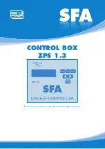
The control system is operated via 6 short travel key switches, the program settings are displayed
on an LCD display. All settings are saved so that they are available when the control system is
restarted. The display language can be changed.
Besides the actual operational parameters, the control system also saves the controlling process
and the pump malfunctions in a record which can be displayed on the LCD display.
2.2 General characteristics
• Clear LCD display
• Hand- Stop- Auto- Function
• 1 acknowledgement button, 2 parameter
select buttons
• Menu which can be switched through
• Internal acoustic alarm
• Programmable operation and collective fault
signal potential-free
• Floating flood control potential-free
• Omnibus fault message potential-free
• Setting via short travel key switches
• Operating hours counter
• Maintenance interval counter
• Pump start counter
• Recording of fault protocol
• Electronic monitoring of the motor current
• Programmable turn-on-delay
• Programmable pump follow-up
• Programmable pump changeover interval
• Switchable service- and ATEX- mode
• Internal pressure sensor
• Level indication in cm
• 2 digital inputs for the thermostatic switch
• 3 digital inputs for the floating switch or reed
sensor
• 1 analogue input for transmitter 4-20mA
• 1 analogue pressure input 0-100(500) mBar
2.3 Technical data
Operating voltage
230V or 400V/AC/50-60 Hz
Voltage of control system
230V/AC/50-60 Hz
Power consumption
env. 6VA
Pressure range
0-1mWs
Turn-on-delay
0-180 sec
Follow-up time
0-180 sec
Runtime monitoring
0-300 sec
Motor current limitation
0.5- 14A
Fault protocol memory
32 memory positions
Maintenance interval counter
0 – 365 days, adjustable
Operating temperature range
-20 - +60°C
Dimensions
180x180x90 mm
Max. pre-fuse
20A
Potential-free alarm contact
3 A max.
Degree of protection
IP 65
Housing
Polycarbonate


