135
UK
7. ACTIVATION
7.1 Prerequisites for commissioning
Before commissioning the pumping station, make sure that the electrical connection for the pumping station and all protective devices has
been correctly performed.
The pump and all protective devices are connected correctly.
• The safety instructions have been followed.
• The operating characteristics have been checked.
• The regulations in force at the place of installation are complied with.
7.2 Application limit
• Avoid running the pump with the valve closed.
• Observe the type of fluids permitted (see section 3.5).
• Dry running, without pumped fluid, must be avoided.
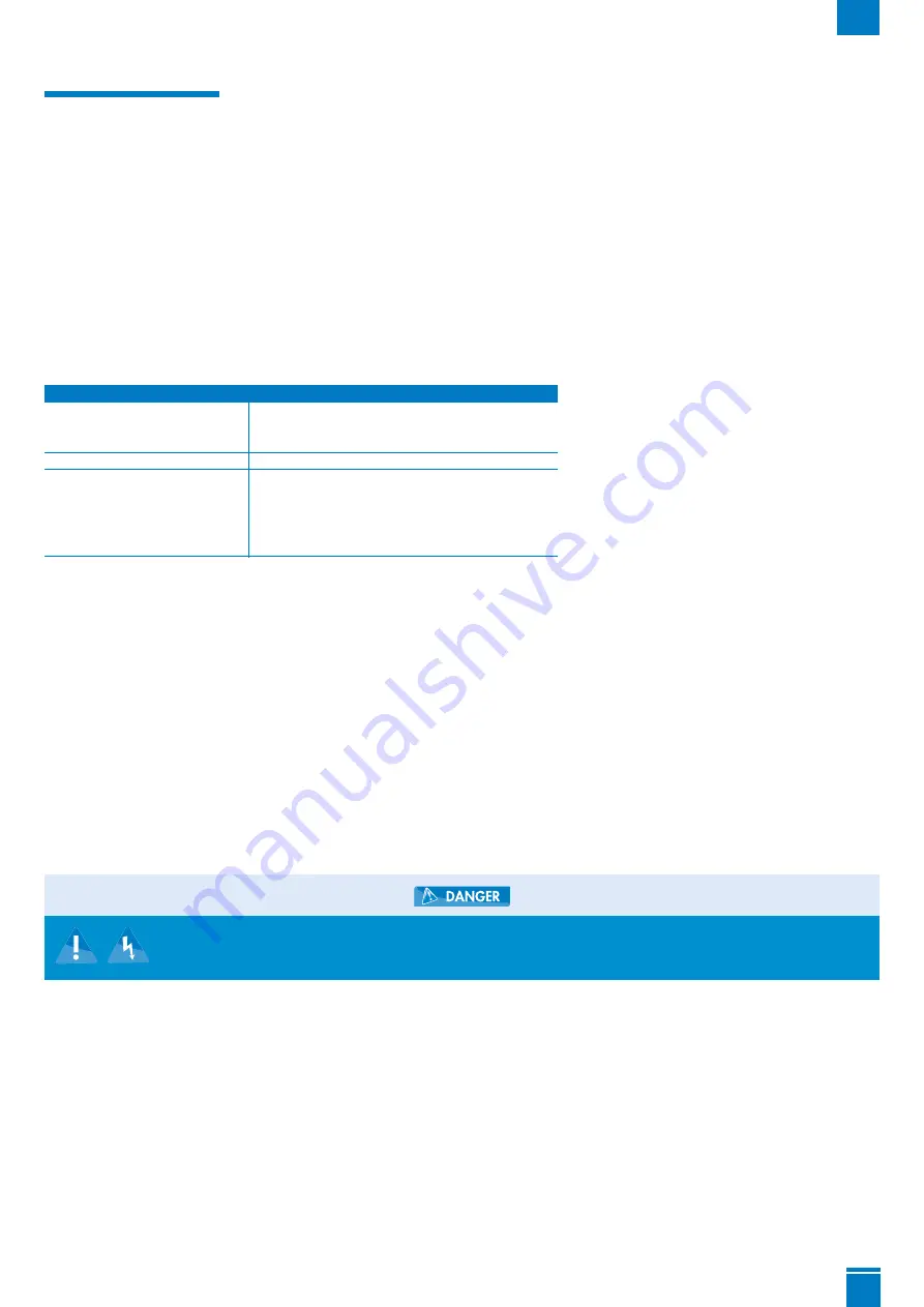
When in use, observe the following parameters and values:
7.3 Starting and stopping
The automatic control starts and stops the pump when a defined level is reached.
The position of each float is set at the factory.
Never change this setting.
In the event of replacement of one or more float switches for maintenance operations, position them as shown in the illustration opposite.
The free length of the floats shall be 150 mm ± 5 from the point of attachment of the cable to the base of the float.
Ensure that the floats move freely.
7.4 Starting frequency
To prevent engine overheating and excessive stress on the engine, seals and bearings, limit the number of starts to 10 per hour.
7.5 Commissioning with the control box
7.6 Operations required for commissioning
1.
Perform a functional and sealing test of the pumping station: once the hydraulic and electrical connections are made, check the connections for
leaks by running water successively through each inlet used. Ensure the device is operating properly and there are no leaks by performing a
water test and observing several start cycles.
2.
Check the various points on the checklist (section 9.1, page 34).
3.
WARNING: Do not run the engine in forced mode (by pressing the key on the keypad) before putting the pump in water. Dry running
damages the grinding system.
7.7 Decommissioning
1.
Close the valves on the supply pipes.
2.
Drain the tank by pressing the forced mode button on the pump.
3.
Close the discharge valve
4.
Switch off the electrical power supply and record the installation.
➜
Il coperchio del modulo di comando non è chiuso correttamente. Rischio di folgorazione!
➜
Richiudere correttamente il coperchio del modulo di comando.
➜
Ricollegare poi la presa di alimentazione.
Parameter
Value
Max. allowed temperature.
40°C
Permitted fluid
up to 70°C for max.
5 minutes per hour
Max. room temperature.
50°C
Operating mode
Intermittent service
SANIFOS
®
110 and SANIFOS
®
250: S3 30 %
Intermittent service
SANIFOS
®
500: S3 50%
SANIFOS® 500 Vortex three-phase : S3 30%


