29
established time. Trigger thresholds can be set only for acceleration components and the trigger
function can be enabled on more axes at the same time according to the OR logic.
When the acceleration component size exceeds an established trigger level, the FTAnalyzer will
detect the related event. In particular, if the trigger function is set up as positive, the FTAnalyzer
will detect the event when the signal exceeds the threshold up the slope; if the trigger function is set
up as negative, the FTAnalyzer will detect the event when the signal exceeds the threshold down
the slope.
After the trigger event, the FTAnalyzer will be waiting for the time established by the user to elapse
and then stop the measure acquisition.
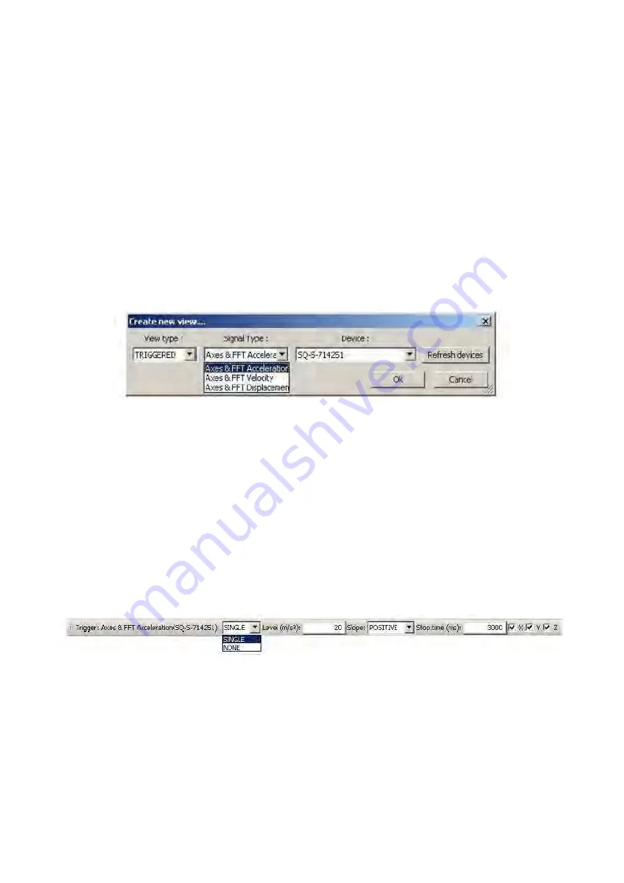
To select the trigger function, click on TRIGGERED in the view type combo box. Measurements
taken this way will be reported both in the time and frequency domain.
To select the value to be measured, select one of the following terms in the Signal Type combo box:
FTAnalyzer: trigger function
Axes & FFT Acceleration: the Graphics area is subdivided into two parts displaying the time
progress and the frequency spectrum of acceleration x, y, z components measured by the
acquisition device;
Axes & FFT Velocity: the Graphics area is subdivided into two parts displaying the time
progress and the frequency spectrum of velocity x, y, z components measured by the acquisition
device;
Axes & FFT Displacement: the Graphics area is subdivided into two parts displaying the time
progress and the frequency spectrum of displacement x, y, z components measured by the
acquisition device.
FTAnalyzer: trigger parameters
To enable the trigger function, set the threshold values in the trigger toolbar as shown below.
Summary of Contents for FastTracer
Page 2: ...Printed in February 2010...
Page 53: ...53 Notes...


