SEON Trooper TL2 Installation Manual Download Page 38

Advanced Setup

3–4

700-0099 R008

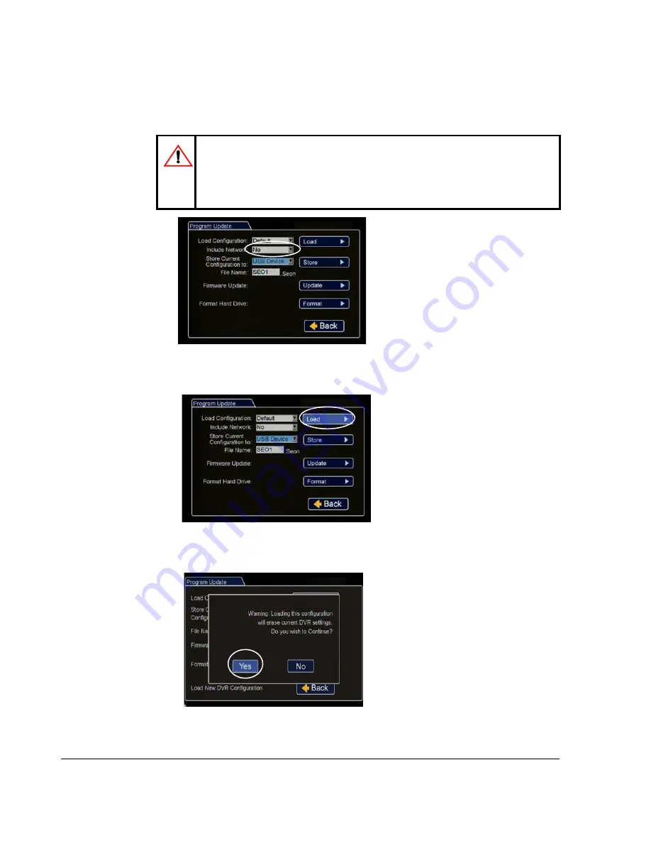
8. From Include Network, select whether or not to overwrite the existing DVR 

network settings with the new configuration settings. The default setting of NO 

keeps your existing network settings.

9. Click Load.

10. In the DVR configuration confirmation dialog, click Yes to proceed.

CAUTION: DVR Communication Disruption Risk

Avoid unintentionally changing the DVR network settings when 

uploading a new configuration. When saving or changing network 

settings, communication with the DVR can be disrupted. 

Figure 3-4

Program Update Menu Include Network

Figure 3-5

Program Update Menu Load

Figure 3-6

Load Configuration: Warning Message

Summary of Contents for Trooper TL2

Page 1: ...Manual Type DVR Firmware Version 2 0 Document Part Number 700 0099 R008 700 0099...

Page 2: ...products and services at www seon com Customer Service Contact Information CAUTION Cautions identify conditions or practices that could result in damage to the unit or other equipment Tip These notes...

Page 3: ...7 12 Volt Installation Details 1 11 1 7 Hardware Installation Final Checklist 1 12 DVR Setup 2 1 DVR Menu Access 2 1 2 2 Basic DVR Configuration Settings 2 2 2 3 vMax Web Laptop Configuration 2 13 2...

Page 4: ...etwork Settings Menu 4 15 4 6 1 Advanced Network Menu 4 16 4 6 2 VMS Servers Menu 4 17 4 6 3 Supervisor Menu 4 18 4 6 4 User Levels Menu 4 19 4 6 5 DDNS Dynamic Domain Name Server Settings Menu 4 20 4...

Page 5: ...n on page 1 9 Wake On Alarm Installation Optional on page 1 10 Diagnostic Button Installation Optional on page 1 11 12 Volt Installation Details on page 1 11 Hardware Installation Final Checklist on p...

Page 6: ...tem see TL4 Installation Diagram on page 1 3 To install the typical TL2 DVR system see TL2 Installation Diagram on page 1 4 Trooper TL DVR with hard drive locking front cover cable cover and mounting...

Page 7: ...3 An optional Smart Reach Cellular Smart Reach Lite Wi Fi or Laptop can be used from the Ethernet input located on the back panel 4 An optional Video Monitor can be used from the video outputs locate...

Page 8: ...uire the adapter harness 3 An optional Laptop can be used from the Ethernet outputs located on the front panel 4 An optional Video Monitor can be used from the video outputs located on the front or ba...

Page 9: ...of heat outlet heater or AC blower Do not operate the DVR in a closed in area orrestrict ventilation in any way The DVR requires air circulation to maintain optimum operating temperature and provide b...

Page 10: ...including lockbox Material steel powder coated black Important Specifications are subject to change without notice Figure 1 1 Trooper TL Dimensions 246 mm 9 11 16 in 134 mm 5 9 32 in 105 mm 4 5 32 in...

Page 11: ...on page 1 6 2 Unlock the door lock and remove the front cover from the unit to access the front panel Verify there is a hard drive inside the DVR 3 Determine where the wiring and camera cables will e...

Page 12: ...9 Connect the necessary cables and components 1 6 2 Camera Installation Install the cameras according to the product documentation that is included with the camera Feed the cable through the large ca...

Page 13: ...es as shown in Figure 1 on page 1 3 1 6 4 Alarm Button Installation To install the alarm button 1 Mount the Alarm Switch into a hole 2 Attach the black wire of the Alarm Switch to the black wire of th...

Page 14: ...alarm input harness 3 Configure the DVR Alarm settings as described in the Alarm Menu on page 4 7 To wire the Wake on Alarm feature with a Diagnostic Button 1 On the Diagnostic Button cable cut the g...

Page 15: ...ation of the DVR However if a power cable extension is required ensure that the voltage drop does not exceed 1 0 volt by using the correct cable size See Table 2 Connections for power cables should be...

Page 16: ...e ignition Configure the DVR to required specifications locally using the trackball mouse and monitor or remotely by accessing vMax Web via Wi Fi or Ethernet using a PC See Basic DVR Configuration Set...

Page 17: ...se to set the configuration settings The password setting can be changed in the System Settings Menu Local access with vMax Web menus Configure the network connection on the computer then connect the...

Page 18: ...not used enter the current time and date Title Display Enter the vehicle number and camera view names to display in overlay text Diagnostic Display If the DVR is used in Canadian fleets select the Cel...

Page 19: ...the Seon Trooper TL4 splash screen appears briefly before the DVR enters live view During recording and live viewing the screen information is dynamic and can include the items shown in Figure 2 2 Fi...

Page 20: ...tion 2 In the Configuration menu click Time Date Figure 2 3 Main Menu Figure 2 4 Configuration Main Menu Note To enter data in OSD fields click with the mouse to display a keyboard Use the on screen p...

Page 21: ...date Note If GPS is installed and GPS time is selected in the Alarm Signal Speed and GPS settings then the date and time automatically update when the GPS detects satellites Auto Daylight Saving shoul...

Page 22: ...rd Delay On Time This sets the time period from when ignition is turned on until the DVRstarts Leave at default to let the bus voltage settle after the bus starts up to prevent voltage drops affecting...

Page 23: ...ss the camera is mounted on the exterior of the vehicle or if you have special requirements Click Back to save the menu settings Figure 2 10 Camera Settings Menu CAUTION Set Unused Cameras Off When a...

Page 24: ...record video flagged at the alarm record settings Speed Quality and Resolution For each alarm select record settings to be used for the duration of the Alarm Turn off unused channels to avoid DVR vid...

Page 25: ...uit rests at 12 VDC and drops to 0 VDC when active Alarm Select the alarm number if the signal is also to be used to trigger an alarm That alarm s input must also be set up in the Alarms menu Click Ba...

Page 26: ...ION Recording over Multiple GPS UTC Reference Settings Whenever the GPS UTC reference setting is edited format the DVR hard drive before the DVR starts recording This is to prevent the DVR from accide...

Page 27: ...figuration file for upload to other DVRs their settings will have to be updated as well See DVR Menu Access on page 2 1 Figure 2 16 Network Settings Menu Users logging on to the DVR locally or remotel...

Page 28: ...from the audio RCA port on the front of the DVR vMax Web Timeout Leave at default 10 minutes Click Back to save the menu settings Figure 2 18 System Settings Menu Select USB Device as the file saving...

Page 29: ...HCP Dynamic Host Configuration Protocol If it is not configured to DHCP or you need to verify the setting then follow these steps to configure your laptop To configure your laptop 1 Navigate to Window...

Page 30: ...s XP select Internet Protocol TCP IPv4 and then click Properties The Internet Protocol Version Properties window appears 4 In the Internet Protocol Properties window select Obtain an IP Address Automa...

Page 31: ...l Area Connection should report limited connectivity using an Automatic Private IP Address Confirm by opening your network connections 4 In very rare instances the laptop may select the same IP addres...

Page 32: ...face The user name is case sensitive 7 Click Ok vMax Web opens with the DVR cameras displaying in Live view 8 See the DVR User manual for details on using the vMax Web Figure 2 25 DVR Login Screen CAU...

Page 33: ...DVR Setup 700 0099 R008 2 17...

Page 34: ...DVR Setup 2 18 700 0099 R008...

Page 35: ...ions DVR Configuration Uploads on page 3 2 Configuration Upload from USB Memory Device on page 3 2 Configuration Uploads in vMax Web on page 3 6 DVR Firmware Updates on page 3 10 Email Notifications o...

Page 36: ...ysical access to the DVR a portable video monitor and a USB mouse To load a configuration update to the DVR the USB memory device must be formatted by a Windows based computer using the FAT file forma...

Page 37: ...figuration menu select the file to upload and click Load Figure 3 2 System Settings Menu Figure 3 3 Loading USB Configuration Important The Load Configuration drop down list only displays the ten most...

Page 38: ...Click Load 10 In the DVR configuration confirmation dialog click Yes to proceed CAUTION DVR Communication Disruption Risk Avoid unintentionally changing the DVR network settings when uploading a new c...

Page 39: ...d update the network settings 16 Turn off the DVR restart the DVR and confirm that the new configuration settings have been applied CAUTION Risk of Network Settings Loss Configurations uploaded to the...

Page 40: ...Power up the DVR using the vehicle ignition 3 Open Internet Explorer and type the DVR IP address in the address bar The Seon default IP address is http 169 254 1 1 4 If necessary agree to Windows Run...

Page 41: ...ring the configuration upload Select the Include Network Settings check box only if you need to overwrite the existing DVR network settings with the new configuration settings 9 In the Program Update...

Page 42: ...click OK to start the configuration upload 13 If necessary agree to Windows Run Add On requests Figure 3 14 Windows File Search Important For consistency Seon recommends that the configuration upload...

Page 43: ...t in the Main_Title field 16 Click Save to save the settings to the DVR 17 If required update the network settings 18 Power down and restart the DVR 19 Login with vMax Web and refresh the vMax Web bro...

Page 44: ...evice with the new firmware version into the USB port on the DVR After the DVR has started go to the System Settings menu Program Update 4 Click Update and in the confirmation window click Yes to proc...

Page 45: ...recording can be viewed remotely and the event can be addressed Set up the DVR to send emails locally or remotely using the following steps On Screen Display Email Setup on page 3 11 vMax Web Email S...

Page 46: ...equired 6 Click Back to save 7 In the System Settings menu set the Disk Full and HD Failure options to E mail 8 Click Back to exit the System configuration menu 9 In the main Configuration menu click...

Page 47: ...om the drop down list and set Email to On 12 Repeat for all alarms requiring email notification 13 Click Back to save and exit the configuration menus If the configured alarm or system events occur an...

Page 48: ...ect the E mail check box for each alarm configuration requiring email notification Figure 3 27 vMax Web E mail settings CAUTION DVR Password Security The default password is 11111111 For security purp...

Page 49: ...em menu select E mail from the Disk Full and HD Failure drop down menus 4 Click Save If the configured alarm or system events occur the email will be sent when the DVR is within range of a Smart Reach...

Page 50: ...Advanced Setup 3 16 700 0099 R008...

Page 51: ...page 4 6 Alarms and Signals Menu on page 4 6 Alarm Menu on page 4 7 Signals Menu on page 4 9 Speed Menu on page 4 10 GPS Settings Menu on page 4 11 Recording Settings Menu on page 4 12 Camera Settings...

Page 52: ...Channel Speed Quality Resolution E mail Wake Speed per Signal Label Level Alarm Signals Speed Display Speed Units Speed Pulse Count Speed Limit Excessive Speed Action Calibrate GPS GPS Display GPS Tim...

Page 53: ...t Set the time in 12 hour or 24 hour format 12 Hour 24 Hour Time Set the time for the DVR 12 00 am to 11 59 pm for 12 Hour format 00 00 to 23 59 for 24 Hour format Date Format Set the preferred date f...

Page 54: ...Description Values Default Start Date Set the week day and month for daylight saving to start 2nd Sunday Mar From Set the time for daylight saving to start 02 00 AM To Set the time for daylight saving...

Page 55: ...ther camera view overlay options Figure 4 4 Titles and Display Menu Table 3 Titles and Display Configuration Items Menu Item Description Value Default Main Title Set a title Main_Title Maximum 32 char...

Page 56: ...c Display Configuration Items Menu Item Description Value Default Voltage Display Display the system input voltage On Off Time Date Display Display the time date display On Off HDD Size Display Displa...

Page 57: ...sec 10 sec Speed For each channel set the recording speed in frames per second to the desired setting A DVR usually records in a mode that conserves hard drive space but increases video speed and qua...

Page 58: ...s line as normally closed N C the red wire must remain at ground when off and trigger on with 12V For example if the alarm input was connected to interior lights of the vehicle the wake function would...

Page 59: ...On screen display text for left turn signal LT maximum 3 characters Signal 2 On screen display text for stop signal STP maximum 3 characters Signal 3 On screen display text for brake signal BRK maximu...

Page 60: ...ontrol Module TCM Calibrate the DVR to the vehicle s speed signal by driving for one mile or kilometer in Calibration Mode The DVR counts the pulses from the speed sensor and then converts a pulse rat...

Page 61: ...reen overlay With a GPS module connected to the DVR the latitude and longitude of the vehicle location are displayed On Off GPS Time Show or hide the GPS time on the main screen overlay Off On UTC Ref...

Page 62: ...ignition signal turns on until the DVR is turned on 0 30 sec 1 5 10 20 30 45 60 min Record Delay Off Time Enables a time delay to continue recording after the ignition signal to the DVR is turned off...

Page 63: ...5 fps Table 9 Record Configuration Items Menu Item Description Value Default Figure 4 12 Camera Settings Menu Table 10 Camera Settings Configuration Items Menu Item Description Value Default Speed Se...

Page 64: ...revent the DVR from generating Video Loss VLoss events for those camera inputs In the DVR Configuration menus disable unused camera inputs as follows Record Settings menu Camera Speed OFF Camera Audio...

Page 65: ...work Settings Menu Table 12 Network Settings Configuration Items Menu Item Description Value Default Setting Type For network settings consult your IT administrator to configure the setting type and I...

Page 66: ...iguration Items Menu Item Description Value Default Integrated VML Set to On to enable the integrated VML feature Off disables the integrated VML feature Off On LAN Range Set the customer network s LA...

Page 67: ...it DVR status messages to all available VMS Servers every 1 to 5 minutes Off 1 2 3 4 5 minutes Port Enter a Port for VMS Heartbeat communication as determined by a qualified network expert Set a value...

Page 68: ...ure 4 17 Supervisor Menu Table 15 VMS Servers Configuration Items Menu Item Description Value Default Supervisor Select Static IP to add a supervisor vehicle DVR s Static IP Address to the Ethernet po...

Page 69: ...evels Configuration Items Menu Item Description Value Default User 1 User 2 to 6 Name Six user names can be configured to have remote access to the DVR These are case sensitive Admin for User 1 Blank...

Page 70: ...NS Settings Configuration Items Menu Item Description Value Default DDNS Dynamic Domain Name Server DynDNS currently supported Maximum 64 characters User Name Set the user name Maximum 32 characters P...

Page 71: ...onfiguration Items Menu Item Description Value Default Disk Full Set to send e mail notification when the disk is full Off E mail HD Failure Set to send e mail notification if the hard drive fails Off...

Page 72: ...down list will only show the most recent 10 configuration files on the USB device Default MEM1 Include Network Select to include network information when the configuration is loaded NO YES Store Curr...

Page 73: ...DVR Configuration Menus 700 0099 R008 4 23 Figure 4 23 Store DVR Configuration to USB Device Message Figure 4 24 Update DVR Firmware Message Figure 4 25 Formatting the Hard Drive Message...

Page 74: ...guration Items Menu Item Description Value Default SMTP Server Set the server name Maximum 32 characters SMTP Port Set the SMTP port 25 1 through 9999 Authentication Set the authentication Login None...

Page 75: ...tems Menu Item Description Value Default One Touch Download Set the video type to be downloaded Alarms Today Time Clip From Date Set the month day and year Depends on the hard drive data From Time Set...

Page 76: ...DVR Configuration Menus 4 26 700 0099 R008...

Page 77: ...ESPECT TO THE PRODUCT S DESCRIBED HEREIN INCLUDING WITHOUT LIMITATION ANY DESCRIPTION OF GOODS OR SERVICES SPECIFICATIONS MODELS DRAWINGS OR DIAGRAMS b DOES NOT ASSUME AND SHALL NOT BE SUBJECT TO AND...

Page 78: ...L 2...

Page 79: ...on may use new or refurbished replacement parts for repairing its products at its sole and arbitrary discretion Seon may replace an entire unit with an equivalent model at its sole and arbitrary discr...

Page 80: ...in connection with the products or this agreement exceed the lower of the suggested list price or the actual price paid for the products regardless of whether such liability arises from contract tort...

Page 81: ...rives if necessary c the parts and repair labor required to complete all warranted repairs are included d Seon will arrange and pay the cost of ground freight between customer s location and the Seon...

Page 82: ...Seon Design Inc Product Warranty W 4 700 0099 R008...

Page 83: ......

Page 84: ...3B Burbidge Street Coquitlam BC Canada V3K 7B2 Telephone Toll Free Telephone 604 941 0880 1 877 630 7366 Fax Toll Free Fax 604 941 0870 1 866 664 3677 Email sales seon com Web site www seon com 700 00...

Reviews: