Site design
Page 8
UltraWave Product Guide
Mounting angle
For microwave pairs with a unit separation of 50 m or less, the microwave units are mounted with
a 5º pitch (toward the ground). This provides the optimum signal strength, when combining the
direct signal and the reflected signal at the receiver unit (see
).
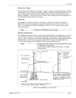
Microwave offsets
The areas immediately above and below the transmitter and receiver antennas are not exposed to
the microwave energy. A microwave offset is used to prevent this unmonitored area from being
vulnerable to undetected intrusions (see
). Offsets prevent intruders from crawling under
or jumping over a microwave unit to gain access to the protected area. The offset distances in the
example drawings are based on a 100 m separation between the transmitter and receiver and a
mounting height of 55 cm (21.5 in.) center of antenna to ground. As the mounting height increases
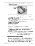
a longer offset is necessary. Different types of offsets are shown in
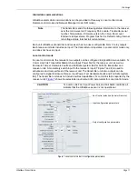
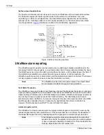
Figure 3 Stacking UltraWave units
Note
The microwave Offset Area describes the distance from the unit’s
mounting position to the point where the beam reaches the
ground’s surface. Only partial coverage is provided inside the
Offset Area. Full coverage begins where the Offset Area ends.
Figure 4 Offset area
receiver units*
transmitter units*
maximum zone height
mounting
heights
via UCM
* When specifying the Frequency Pairs for stacked UltraWave sensors do not use consecutive, adjacent numbers.
(e.g., Use Frequency Pairs 1, 3, 5 rather than 1, 2, 3 to ensure optimal signal isolation for each sensor pair.)
partial coverage
partial coverage
beam centerline
full
coverage
detection
zone
offset area
4.74 m
(15.6 ft.)
55 cm
(21.5 in.)


