Site design
UltraWave Product Guide
Page 11
Alarm data communications
UltraWave alarm data communications can be provided in three ways, Local control mode,
Remote control mode and Network Manager mode (NM mode).
Each unit UltraWave (transmitter and receiver) has two user-configurable Form C relay outputs.
Each receiver unit also includes an input. The transmitter unit operates in Local control mode only,
and does not have an input.
Local control mode
In Local control mode, the receiver’s two outputs can be configured to signal Microwave Alarm, Tx
Comm Link Fail, Transmitter Mismatch and Input Power Fail for the receiver unit; as well as
Enclosure Tamper, Hardware Faults and Fail Safe (system fail) for both the transmitter and
receiver units. A momentary switch input to the receiver’s input (T6 pins 7 and 8) is used to
activate an electronic self-test of the receiver unit. The transmitter unit’s two outputs can be
configured to signal Enclosure Tamper, Input Power Fail, Hardware Faults and Fail Safe (system
fail). The transmitter unit does not include self-test capabilities (Tx comm link fail is reported by the
receiver unit).
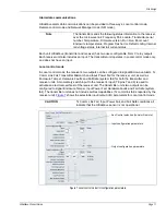
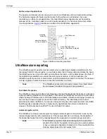
shows the selectable input/output (I/O) parameters for Local control mode.
Note
The transmitter sends the following status information to the receiver,
over the microwave link: Frequency Pair, Locale, Transmitter serial
number, Temperature, Firmware version, Run time, Boot count,
Enclosure tamper status, Program Flash error, Default config, Internal
rail voltage status, Internal rail current status.
CAUTION
Tx Comm Link Fail, Input Power Fail, and Fail Safe conditions all
indicate that the UltraWave sensor is not operational.
Figure 7 Local control mode I/O configuration parameters
Aux Control selection (Local or Remote)
Input configuration parameters
Output configuration parameters


