UltraWave Product Guide
Page 21
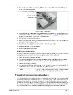
2. Reverse the post collar so the flat side of the collar is to the outside, and reattach the post
collar to the mounting bracket.
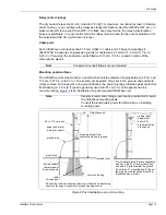
3. Hold the UltraWave unit against the mounting surface and measure the mounting height of the
unit from the center of the antenna to the ground’s surface (see
). Mark the mounting
surface at the centers of the two holes in the post collar.
4. Drill two holes in the mounting surface.
5. Remove the post collar from the mounting bracket, and use appropriate fasteners to attach the
post collar to the mounting surface.
6. Re-attach the mounting bracket and UltraWave unit to the post collar.
7. Measure and verify the mounting height.
8. Mount the second UltraWave unit.
Initial surface-mount alignment
To ensure optimal performance, it is critical that the UltraWave transmitter and receiver are aimed
directly toward each other, and that the mounting height is correct for both units.
1. Verify the mounting heights of both units.
2. If required, loosen the mounting hardware on the post collars, and install shims so that the
UltraWave transmitter and receiver point directly at each other (horizontal adjustment).
3. Tighten the mounting hardware.
4. If required, loosen the four bolts attaching the post collar to the mounting bracket and aim the
units toward each other (in the vertical axis). Re-tighten the bolts.
Transmitter/receiver wiring connections
The UltraWave wiring connections are made on removable terminal blocks. The screw terminals
accept wire sizes from 12 to 24 AWG, with a 6.4 mm (0.25 in.) strip length. Remove the terminal
blocks to make the wiring connections. Reinstall the blocks after the connections are complete,
and verified. The DC power input is made on T3 and the input/output connections are made on T6.
The receiver’s auxiliary (AUX) input is available when using Remote control mode (network alarm
data communications). The receiver’s self-test input is available in Local control mode (relay
Figure 17 Surface mounting setup
Note
If the microwave pair is separated by 50 m or less, adjust the
pitch of both units to a 5º angle (toward the ground).
post collar (reversed)
mounting bracket
7 mm (0.25 in.) mounting holes


