background image

UltraWave Product Guide

Page 43

Verifying the UltraWave alignment

If the UltraWave sensor is encountering detection problems it is possible that one of the unit’s may 
be out of alignment. The UltraWave receiver includes a received signal strength indicator (RSSI) 
as an alignment aid (LEDs D6 - D13).

1. Remove the lower cover from the receiver unit.

2. Press and hold the tamper switch, while observing the RSSI (LEDs D6 - D13). Do not obstruct 

the receiver’s antenna while observing the RSSI.

3. Note the received signal strength (e.g., LED D7 ON).

4. Adjust the horizontal and vertical alignment of the receiver unit slightly to determine if the 

received signal can be improved. Recheck the RSSI level.

5. Adjust the horizontal and vertical alignment of the transmitter unit slightly to determine if the 

received signal can be improved. Recheck the RSSI level at the receiver unit.

6. Once the alignment is complete, connect the UCM and select the Recalibrate button.

7. Replace the lower cover on the receiver unit.

Figure 34 LEDs D6 - D13 RSSI alignment aid

D6 - maximum received signal strength

D13 - minimum received signal strength

D9 - minimum operational signal strength

(operational range D9 to D6)

Summary of Contents for UltraWave E4FG0101

Page 1: ...Product Guide UltraWave Microwave Detection Sensor E4DA0402 001 Rev E August 27 2019 ...

Page 2: ...oit pas produire de brouillage préjudiciable et 2 il doit accepter tout brouillage reçu y compris un brouillage susceptible de provoquer un fonctionnement indésirable USA FCC Identification Number transmitter I5T E4EM0101 receiver I5T E4EM0201 FCC Certification This device complies with part 15 of the FCC Rules Operation is subject to the following two conditions 1 This device may not cause harmfu...

Page 3: ...ts surfaces 13 Surface mount applications 14 UltraWave alarm reporting 14 Fast Alarm Response 14 Automatic gain control 14 2 Installation 15 Mounting the UltraWave units 17 Post mounting procedure 18 Initial post mount alignment 19 Surface mounting 20 Surface mounting procedure 20 Initial surface mount alignment 21 Transmitter receiver wiring connections 21 T3 power input 22 T6 receiver unit input...

Page 4: ...the Auxiliary I O control mode 35 Auxiliary self test input 35 Input configuration procedure Local control mode 36 Input configuration procedure Remote control mode 36 Output relays 37 Output relay setup Local control mode 37 Output relay setup Remote control mode 37 Receiver calibration 38 Optimizing the alignment 38 System verification tests 39 4 Maintenance 41 UltraWave unit maintenance 41 Ultr...

Page 5: ...eting the site survey Include dimensions elevations and the locations of any objects noted during the survey Once the site drawings are complete carefully plot each microwave zone Zone placement zone length and offsets are critical factors in the design of a microwave sensor system The UltraWave system requires a straight flat detection zone free of obstacles and depressions The zone must be compl...

Page 6: ... closely mowed grass For a low security zone the maximum zone length is 200 m 656 ft and the maximum distance between the transmitter and receiver is 200 m The terrain must be level to grade 23 cm 9 in and the surface must be paved or covered with crushed stone or hard packed dirt or clay or closely mowed grass Zone height The height of the microwave field is approximately equal to the minimum req...

Page 7: ...ations for the optimum Threshold settings Figure 2 illustrates the Height Calculator tool Note The Universal Configuration Module UCM includes a height calculator tool that determines microwave offsets mounting heights beam width and clearance requirements based on unit separation Use the Height Calc tool when planning an UltraWave zone Figure 2 UCM Height Calculator tool Tx Rx separation configur...

Page 8: ...a 100 m separation between the transmitter and receiver and a mounting height of 55 cm 21 5 in center of antenna to ground As the mounting height increases a longer offset is necessary Different types of offsets are shown in Figure 5 Figure 3 Stacking UltraWave units Note The microwave Offset Area describes the distance from the unit s mounting position to the point where the beam reaches the grou...

Page 9: ...connected at one end of the perimeter and run around in a single direction Figure 6 illustrates a 24 VDC power supply with 16 AWG power cables in a 360 m high security UltraWave perimeter Figure 5 Offset arrangement examples Note Senstar recommends installing a low resistance 5 or less earth ground at each unit Consult the local electrical codes for grounding information Note The perimeter length ...

Page 10: ...ft 18 AWG 24 VDC not recommended N A 48 VDC 6 864 m 2834 ft 200 m 656 ft 200 m 656 ft 18 AWG 24 VDC not recommended N A 48 VDC 5 1000 m 3280 ft Table 3 Power supply power cable loads 18 AWG power supply connected to one end of perimeter unit separation Rx Tx detection zone length wire gauge AWG power supply output voltage number of UltraWave pairs perimeter length 100 m 328 ft 90 m 295 ft 16 AWG 2...

Page 11: ... 8 is used to activate an electronic self test of the receiver unit The transmitter unit s two outputs can be configured to signal Enclosure Tamper Input Power Fail Hardware Faults and Fail Safe system fail The transmitter unit does not include self test capabilities Tx comm link fail is reported by the receiver unit Figure 7 shows the selectable input output I O parameters for Local control mode ...

Page 12: ...ay or open collector When an alarm occurs on a connected sensor the corresponding UltraLink I O output is activated see NM Mode on page 49 for additional details Silver Network specifications Silver Network specifications Data rate fixed 57 6 k bps Maximum 60 devices spread over up to 4 independent network loops Two communication Channels Side A Side B Response time 1 second or less from alarm sou...

Page 13: ...able to rotate or move For areas where the ground freezes the posts must be protected against potential frost heaving A 2 5 m 8 ft post is generally used with 91 cm 3 ft of the post buried in a concrete footing Figure 8 is an illustration of a post mounted UltraWave unit Note Conduit and conduit fittings are not included Note Senstar recommends hiring a local fencing contractor to install the Ultr...

Page 14: ...r s advanced signal processing algorithms when enabled This causes the UltraWave receiver to function like a classic analog microwave sensor With Fast Response enabled UltraWave will trigger an alarm as soon as the microwave signal exceeds the Threshold setting The Fast Response channel provides early alarm notification but can also cause an increase in the nuisance alarm rate NAR Fast Response is...

Page 15: ...d receiver units are almost identical with only minor differences in component layout Figure 11 shows an UltraWave receiver and illustrates the unit s features The receiver s diagnostic activity LEDs are listed in Table 5 Note DO NOT remove or tighten the four screws on the antenna compartment To access the transmitter receiver circuit card assembly remove the four screws on the circuit card cover...

Page 16: ...ARM LED ON output 2 activated sensor alarm by default configurable in Local control D16 POWER LED ON input power fault D25 SUPERVISION LED ON output 1 activated supervision alarm by default configurable in Local control Table 5 UltraWave diagnostic activity LEDs Note LEDs D6 to D13 also function as a received signal strength indicator RSSI to aid in the final alignment of the UltraWave system The ...

Page 17: ...ess each UltraWave unit should be mounted with a 5º pitch toward the ground The 5º pitch combines the reflected signal and the direct signal to create the strongest received signal possible for short range applications see Figure 8 and Figure 16 The mounting bracket and the post collar each include a central alignment hole that when lined up create a precise 5º angle The calibration testing will d...

Page 18: ...collar gear clamp E4KT0300 post mounting kit mounting bracket hardware one set per UltraWave unit compression glands kit includes two sets 4 each in flat washers lock washers in X 20 hex nuts alignment holes for 5º mounting angle Pass the gear clamp through the slots in the post collar Attach the mounting bracket assembly to the UltraWave unit ...

Page 19: ... post mount alignment For optimal performance ensure that the UltraWave transmitter and receiver are aimed directly toward each other and that the mounting height is correct for both units see Figure 16 1 Measure and verify the mounting heights of both units center of antenna to ground 2 If required loosen the transmitter s gear clamp slightly and then carefully aim the transmitter directly at the...

Page 20: ...he mounting surface Surface mounting procedure 1 Using an 11 mm 7 16 in wrench remove the hardware attaching the post collar to the mounting bracket Figure 16 UltraWave alignment CAUTION For surface mount applications the two mounting surfaces must face toward each other Surface mounted UltraWave units cannot be rotated in the horizontal axis If required use shims to adjust the horizontal alignmen...

Page 21: ...f required loosen the mounting hardware on the post collars and install shims so that the UltraWave transmitter and receiver point directly at each other horizontal adjustment 3 Tighten the mounting hardware 4 If required loosen the four bolts attaching the post collar to the mounting bracket and aim the units toward each other in the vertical axis Re tighten the bolts Transmitter receiver wiring ...

Page 22: ...f the receiver unit Self test activation Figure 18 Relay output power input and ground connection wiring Rx Tx Figure 19 Transmitter receiver wiring connections ground connection machine screw ground wire T7 PCB ground PCB T3 power input 12 to 48 VDC T6 input output connections ground connection details Customer supplied T6 T3 1 2 3 4 5 6 7 8 1 2 NC COM NO NC COM NO T6 T3 1 2 3 4 5 6 7 8 1 2 NC CO...

Page 23: ...ures and supervision resistors Any change in the input s status is reported to the SMS Cable ports Each UltraWave unit includes two 22 mm 0 875 in cable ports and two compression glands Pull the cables through the compression glands into the enclosure and through the locking nut Then install the compression glands in the cable ports After making the wiring connections hand tighten the compression ...

Page 24: ... on the NIC T1 and then connect the NIC s power output T2 to the power input on the transmitter receiver unit T3 Silver Network alarm data communications Installing the Network interface card NIC 1 Remove the lower cover from the receiver enclosure 2 Disconnect the power at T3 3 Remove and retain the hardware from the two standoffs on the receiver circuit card 4 Insert the 20 pin expansion header ...

Page 25: ... T1 on PCB use single point grounding connect one end of the shield trim back the other end and leave it disconnected ground connection T3 receiver power input T6 input output see Figure 10 AUX input output 1 output 2 NIC mounting hardware X 2 T3 NIC expansion header solder side plug into T1 on receiver T1 Ethernet connection T2 PoE NIC power output to receiver PoE NIC supplies power to the receiv...

Page 26: ...nt grounding connect only one end of shield 1 1 2 2 3 3 4 4 5 5 R X B R X B G N D T X B T X B R X A R X A G N D T X A T X A 1 1 2 2 3 3 4 4 5 5 1 2 3 4 5 1 2 3 4 5 1 1 2 2 3 3 4 4 5 5 1 2 3 4 5 1 2 3 4 5 1 2 3 4 5 1 2 3 4 5 R X B R X B G N D T X B T X B R X A R X A G N D T X A T X A R X B R X B G N D T X B T X B R X A R X A G N D T X A T X A R X A R X A G N D T X A T X A 1 2 3 4 5 R X B R X B G N ...

Page 27: ... 2 km 1 4 miles singlemode fiber optic 10 km 6 2 miles TXA RXA TXB RXB TXB RXB TXA RXA 1 1 2 2 3 3 4 4 5 5 R X B R X B G N D T X B T X B R X A R X A G N D T X A T X A 1 2 3 4 5 1 2 3 4 5 1 2 3 4 5 1 2 3 4 5 R X A R X A G N D T X A T X A R X B R X B G N D T X B T X B 1 2 3 4 5 maximum 60 devices first receiver second receiver last receiver Network Interface Unit to Network Manager maximum distance ...

Page 28: ...5 rather than 1 2 3 To facilitate the wiring connections it is recommended that the receivers be mounted on one post and the transmitters be mounted on another post Figure 27 illustrates the wiring connections for a double stacked UltraWave configuration Figure 3 illustrates a triple stack UltraWave system Figure 26 Silver Network Ethernet wiring diagram maximum 60 receivers processors first recei...

Page 29: ...pper transmitter shield shield shield upper receiver lower transmitter lower receiver to NIU or next Silver device to NIU or next Silver device see lower transmitter for connection details see lower receiver for connection details auxiliary input N A output 1 NO output 2 NO Local control mode Use single point grounding connect one end of shield trim back and leave the other end disconnected 12 to ...

Page 30: ...Page 30 UltraWave Product Guide ...

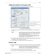
Page 31: ...s must match specify the Frequency Pair transmitter and receiver settings must match enter the Transmitter Serial Number set the detection Thresholds use the UCM Height Calculator tool to determine the optimum detection Thresholds The UltraWave transmitter setup requires the following configuration settings specify the Locale FCC for North American applications ETSI for European applications trans...

Page 32: ... transmitter receiver units you are prompted to select the sensor s Locale region of operation FCC for North American operation or ETSI for European operation Make the selection based on the country in which the unit is installed The UltraWave will not operate until both the transmitter and receiver have the Locale specified select the Network Type select the Device Type specify the connection sel...

Page 33: ...o the receiver unit select the Config tab 2 Set the receiver s Locale and Frequency Pair to match the transmitter s settings Figure 30 UCM Config tab transmitter unit Note Both the transmitter and receiver must use the same Frequency Pair and Locale Nearby UltraWave sensors and stacked configurations must use different Frequency Pairs Do not assign consecutive Frequency Pairs to UltraWave sensors ...

Page 34: ...UCM Config tab receiver unit Note Fast Response Enable is a parameter that is used to bypass the sensor s advanced signal processing algorithms When Fast Response is enabled UltraWave functions like a classic analog microwave sensor An alarm is triggered when the microwave signal exceeds the Threshold setting The Fast Response channel provides early alarm notification but can also cause an increas...

Page 35: ...u must specify the baud rate all devices on a Crossfire network must communicate at the same baud rate For the Silver Star you specify the IP Address the Subnet Mask and the Gateway IP Address if required 3 Save and download the configuration changes to the processor Specify the Auxiliary I O control mode Specify the control mode for the UltraWave units Local control or Remote control 1 Select the...

Page 36: ...tab on the UCM window 2 Set the Filter Window 3 Save and download the configuration changes to the receiver Input configuration procedure Remote control mode 1 Select the Aux Cfig tab on the UCM window 2 From the Supervision drop down select the desired supervision scheme for the input Input option UCM selection Alarm relay Supervision relay R1 R2 unsupervised NO single resistor supervision NO NC ...

Page 37: ...Save and download the configuration changes to the UltraWave unit Output relay setup Remote control mode In Remote control mode the receiver s relays are controlled by the security management system to operate auxiliary equipment as output control points e g to activate lights doors sirens CCTV equipment etc The transmitter s relays operate only in Local control mode You configure the relays respo...

Page 38: ...ved signal and good detection sensitivity However it may be possible to improve the received signal by adjusting the transmitter and receiver units alignment 1 Note the receiver s displayed Gain value once the self calibration is complete CAUTION Ensure that the microwave detection zone is not disturbed during the calibration process Figure 32 UCM Status tab Note See Verifying the UltraWave alignm...

Page 39: ...ity to which they apply Running a UCM Response plot during the testing will provide a record of the test results along with an indication of the signal magnitude created by the test subject Typically the Crawl Target Threshold is exceeded first as the test subject enters the microwave field The Upright Target Threshold may also be exceeded depending on the type of test Figure 33 is a flow chart of...

Page 40: ...t an alarm with each test 6 When each test results in an alarm use the current Threshold settings and monitor the system for nuisance alarms If the NAR is acceptable use the current Threshold settings Figure 33 UltraWave verification test flow chart Recalibrate button set the Thresholds correct problems microwave alarms lower Threshold s monitor NAR too many NAs calibration complete verify install...

Page 41: ...f the receiver unit select the Recalibrate button UltraWave site maintenance After major seasonal changes and following periods of severe weather Verify that there are no objects within the microwave zone or inside the required area of clearance Ensure that standing water cannot accumulate within the microwave zone i e puddles and that running water cannot flow through the zone Check the line of s...

Page 42: ... switch input for approximately two seconds the switch must be closed for a minimum of the time specified in the Filter Window parameter The self test is successful if the receiver signals a microwave alarm For UltraWave systems that operate in Remote control mode use the security management system to activate the self test input The self test is successful if the receiver signals a microwave alar...

Page 43: ...te the received signal strength e g LED D7 ON 4 Adjust the horizontal and vertical alignment of the receiver unit slightly to determine if the received signal can be improved Recheck the RSSI level 5 Adjust the horizontal and vertical alignment of the transmitter unit slightly to determine if the received signal can be improved Recheck the RSSI level at the receiver unit 6 Once the alignment is co...

Page 44: ...Page 44 UltraWave Product Guide ...

Page 45: ...11 4 cm 1 7 8 to 4 1 2 in Weight 0 9 kg 2 lbs each unit Transmitter Receiver Operating voltage 12 48 VDC Microwave carrier frequency ETSI 24 150 24 250 GHz FCC 24 075 24 175 GHz Separation distance max transmitter receiver high security 100 m 328 ft transmitter receiver medium security 150 m 492 ft transmitter receiver low security 200 m 656 ft Detection zone length max high security 90 5 m 297 ft...

Page 46: ...Page 46 UltraWave Product Guide ...

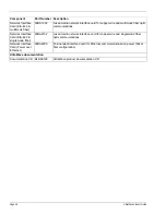
Page 47: ...lver Network Interface Unit 00EM0200 Silver Network data converter for EIA 422 and multimode fiber optic applications Silver Network Interface Unit 00EM0201 Silver Network data converter for EIA 422 and singlemode fiber optic applications Network Manager 00FG0200 Network Manager CD containing Network Manager application software for the Silver Crossfire MX VoE and Sennet networks Windows applicati...

Page 48: ...ce Card EIA 422 singlemode fiber 00BA2102 mixed media network interface card for copper wire and singlemode fiber optic communications Network Interface Card Power over Ethernet 00BA2200 PoE network interface card for Ethernet communications and power Silver Star configuration UltraWave documentation documentation CD E4DA0120 UltraWave product documentation CD Component Part Number Description ...

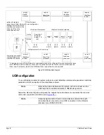
Page 49: ... an UltraLink I O system operating in NM Mode with eight connected sensors and a temporary connection to a Silver Network Manager to enable remote maintenance access Note NM Mode supports only the Silver Loop configuration The Silver Star configuration PoE NIC cannot be used with NM Mode Note The UltraLink I O output point assignments for each node are made at the sensor level through a direct UCM...

Page 50: ...or maintenance access the UltraLink I O processor must be taken UltraLink I O processor card 1 O P card 3 O P card 4 O P card 2 O P UltraLink I O output modules A side B side FlexPS processor FlexZone processor UltraWave receiver UltraWave receiver processor OmniTrax processor OmniTrax processor XField FlexZone processor node 1 node 2 node 3 node 4 node 5 node 6 node 7 node 8 Comm Fail O P alarms ...

Page 51: ...UltraWave Product Guide Page 51 Figure 36 Setting up the Remote Configuration outputs select the Remote Cfig tab select the arrow and use the drop down menu to specify the appropriate output ...

Page 52: ...Page 52 UltraWave Product Guide ...

Reviews: