


27
Problems that may occur during operation
If a problem occurs that is not listed in the above table or cannot be solved
with the proposed solutions:
y
Register on the Sennheiser homepage at www.sennheiser.com/net1 and
describe the problem in the “Support” section
or
y
contact your local Sennheiser agent.
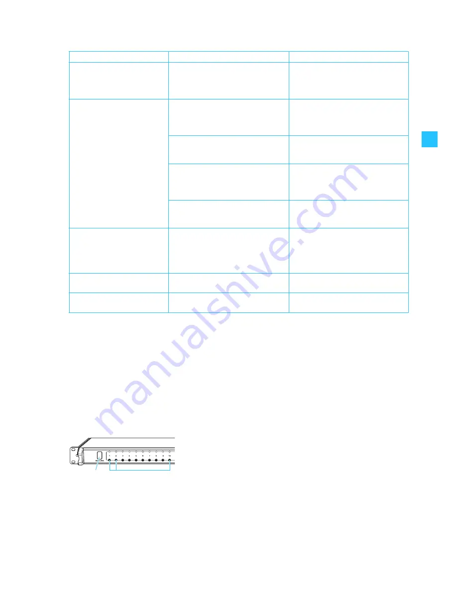
Restarting the NET 1
Even if the NET 1 is rack-mounted, it can easily be restarted as follows:
왘
Simultaneously press the channel buttons 1, 2 and 10 and keep them
pressed for approx. 3 seconds.
The NET 1 restarts.
Problem
Possible cause
Possible solution
NET 1 has assigned the same
frequency to several evolution
wireless G2 receivers
You have connected more receivers
from one frequency range than there
are free channels in the channel bank.
Only connect as many receivers from
one frequency range as there are free
channels in the channel bank and
restart the frequency scan.
It is not possible to transfer the
frequency to the portable
transmitters or receivers (IEM)
The device does not have the latest
firmware installed.
Update the firmware of the transmitter
(see the Instructions for use of the
“Wireless Systems Manager”
software).
The device is not within the range of
the infrared interface.
Place the device at a distance of
approx. 10 cm in front of the infrared
interface (see page 20 and page 22).
The infrared interface of the NET 1 is
not yet ready for transferring the
frequencies. The NET 1 is still in scan
mode.
Press the
MODE
button
to cancel the
scan (see “Cancelling the frequency
scan on the NET 1” on page 23).
The device is from a different frequency
range.
Use a device that matches the
frequency range of the rack-mount
device.
The red “ERROR” LED
flashes
rapidly for approx. 3 seconds
and the “CHANNEL” LED
for
the device lights up
permanently
The frequency transfer to the device
has failed.
The device is from a wrong frequency
range.
Repeat the frequency transfer
(see page 20, page 22 and page 24)
with a device from the matching
frequency range.
The NET 1 does not react
Restart the NET 1 (see “Restarting the
NET 1” on page 27).
The yellow “REMOTE” LED
does not light up
Communication between the NET 1 and
the PC is disturbed.
Check the connections and cables as
well as the PC settings.


