background image

10

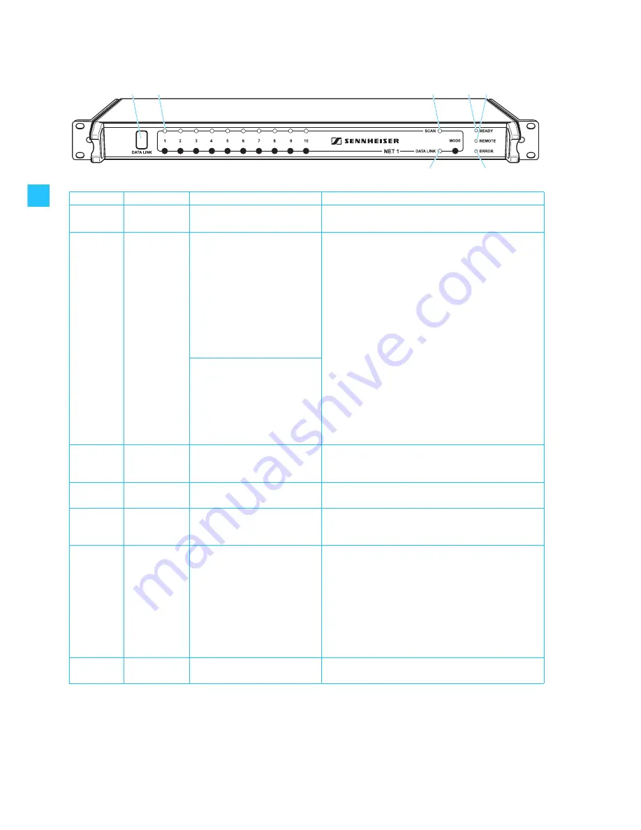
LEDs on the front panel of the NET 1 


LED 

Color of LED

LED lights up permanently

LED...

IR 

interface

backlit in blue

NET 1 is ready to transfer the 
frequencies and settings.

CHANNEL

(1 to 10 )

green

NET 1 has detected the conncted 
devices.

...flashes slowly:

Rack-mount receivers
After the frequency scan, NET 1 indicates the receivers 
belonging to the frequency range of the receiver that has 
performed the scan.

Rack-mount transmitters (IEM):
After the frequency scan with a portable receiver (IEM) 
and the frequency transfer to the transmitters (IEM) of 
the correspondingfrequency range, the receivers (IEM) can 
now be configured.

IR frequency transfer is 
successfully completed

...flashes rapidly:

NET 1 is ready to transfer the frequencies and settings to a 
portable device.

...flashes once every second:

The firmware of the connected evolution wireless G2 
device is not the latest (see the instructions for use of the 
“Wireless Systems Manager” software).

SCAN

yellow

With the

 MODE

 button pressed, 

NET 1 indicates that it is ready for 
scanning

...flashes slowly:

A frequency scan is being performed.

READY

green

NET 1 is ready for operation

...flashes:

NET 1 has been switched on and is being initialized.

REMOTE

yellow

NET 1 is PC controlled or 
controlled via an additional NET 1 
(“remote operation”)

ERROR


red

...flashes rapidly for approx. 3 seconds:

y

An error has occured during IR data transfer (e.g. wrong 
frequency range of the device); data transfer must be 
repeated.

y

The

 MODE

 button is being pressed but NET 1 cannot 

switch to scan mode because:

 – no receiver is connected.

 – NET 1 is PC controlled or controlled via an additional 

NET 1 (“remote operation”).

DATA LINK

yellow

A device is connected.

...flashes slowly:

NET 1 is ready to transfer the frequencies and settings.

Summary of Contents for NET 1

Page 1: ...Instructions for use NET 1...

Page 2: ......

Page 3: ...e 17 Performing a frequency scan for wireless monitoring systems IEM 18 Performing a frequency scan for wireless microphone systems 21 Operation with 3000 5000 series systems 24 Mixed operation of evo...

Page 4: ...d use caution when moving the cart apparatus combination to avoid injury from tip over 13 Unplug this apparatus during lightning storms or when unused for long periods of time 14 Refer all servicing t...

Page 5: ...ings into this device as they may touch dangerous voltage points or short out parts that could result in fire or electric shock Never spill liquids of any kind onto the device Should spillage occur un...

Page 6: ...rmine that the device is in safe operating order Accompanying documentation In addition to these instructions please also refer to the y instructions for use of the rack mount and portable devices y i...

Page 7: ...real time monitoring as well as remote controlling of all relevant device parameters during live operation ensuring an excellent overview of the system at all times In addition the WSM software allows...

Page 8: ...y Instructions for use of the NET 1 y NET stickers to mark the receivers and transmitters that have had the latest firmware installed after you have updated them from the supplied CD ROM y 1 CD ROM w...

Page 9: ...switch 3 pin IEC power connector 5 x sub D socket for connecting EM 3532 twin receivers LAN 2 Ethernet connection Neutrik RJ 45 socket LAN 1 Ethernet connection Neutrik RJ 45 socket DATA LED yellow E...

Page 10: ...es once every second The firmware of the connected evolution wireless G2 device is not the latest see the instructions for use of the Wireless Systems Manager software SCAN yellow With the MODE button...

Page 11: ...n the rear panel of the NET 1 LED Color of LED LED lights up permanently LED DATA Ethernet yellow NET 1 is connected to a PC or an additional NET 1 flashes rapidly Data is being transferred within the...

Page 12: ...might cause stains when they come into contact with other synthetics Despite a thorough testing of the synthetics used by us we cannot rule out the possibility of staining Ensure that the base of the...

Page 13: ...For multi channel systems you can daisy chain several NET 1 devices Make sure that within the network the number of connected devices per frequency range does not exceed the number of free preset freq...

Page 14: ...as viewed from the rear of the receiver common data interface DATA IN OUT as shown in the diagram below Connecting several NET 1 Connect two NET 1 via the sockets LAN 1 and LAN 2 using an Ethernet cab...

Page 15: ...he PC using an Ethernet cable Notes y It is also possible to connect up to five NET 1 to a PC using a switch or a router with switching function y Do not use a network hub Attempting to use a hub with...

Page 16: ...nstructions for use of the software Once communication between the PC and the NET 1 is working properly the yellow REMOTE LED on the NET 1 and on all daisy chained NET 1 lights up permanently Updating...

Page 17: ...er software The rack mount receivers and transmitters IEM may well have different frequency ranges Performing a frequency scan in Stand Alone operating mode With the frequency scan the NET 1 searches...

Page 18: ...ne the desired frequency range for the frequency scan you first have to select a rack mount transmitter IEM belonging to the desired frequency range as follows Press the corresponding channel button T...

Page 19: ...transfer open the cover of the portable receiver IEM Place the receiver IEM in front of the infrared interface The distance between the infrared interface of the NET 1 and the infrared interface of t...

Page 20: ...front of the infrared interface or select another receiver from the matching frequency range and place this transmitter in front of the infrared interface When all the frequencies have been successful...

Page 21: ...ck mount device from each of the frequency ranges The CHANNEL LEDs assigned to these devices light up When two NET 1 are daisy chained pressing the MODE button automatically determines the master NET...

Page 22: ...than free channels are available in one channel bank the NET 1 re assigns the last frequency assigned to the subsequent receivers After the frequency scan the NET 1 indicates that you can transfer th...

Page 23: ...e portable transmitter in front of the infrared interface or select another transmitter from the matching frequency range and place this transmitter in front of the infrared interface When all the fre...

Page 24: ...n the NET 1 so as to avoid interference from extraneous light Switch on the transmitter as described in the instructions for use of the transmitter Place the transmitter in front of the infrared inter...

Page 25: ...less G2 series systems and 3000 5000 series systems please refer to the instructions for use of the Wireless Systems Manager software Note The compander systems are not compatible Therefore synchroniz...

Page 26: ...onnecting the devices on page 13 One of the receivers RX 1 or RX 2 of the connected EM 3532 twin receiver is not being detected due to the fact that the receiver was switched off when the NET 1 was sw...

Page 27: ...the latest firmware installed Update the firmware of the transmitter see the Instructions for use of the Wireless Systems Manager software The device is not within the range of the infrared interface...

Page 28: ...C adresses are indicated on the type plate CAT 5 or higher Use only shielded cable 100 m UART 1 infrared interface Max cable length lnsulation 10 x RS 485 via RJ 10 for connecting ew G2 series devices...

Page 29: ...le shielded Length 2 m 515674 Special sub D cable Length 1 5 m 054324 Power cord with EU plug 054325 Power cord with US plug 057256 Power cord with UK plug 086363 Device feet 089540 Rack mount ears 52...

Page 30: ...arantee CE Declaration of Conformity This equipment is in compliance with the essential requirements and other relevant provisions of Directives 89 336 EC or 73 23 EC The declaration is available on t...

Page 31: ......

Page 32: ...Sennheiser electronic GmbH Co KG 30900 Wedemark Germany Phone 49 5130 600 0 Fax 49 5130 600 300 www sennheiser com Printed in Germany Publ 03 07 516511 A04...

Reviews: