background image

SMD 989

– User Manual 

Page 51 (105)


Description:

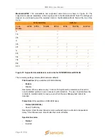
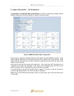
 When set to enable a rate adaption is applied to the DVB-S2X.mode.  When 

disabled the rate adaptation is not active. Rate adaptation forces the modulator to add or 
remove  null  packets  and  re-stamp  PCRs  in  order  to  match TS  bitrate  to the  modulation 
payload  rate.  Disabling  rate  adaptation  is  desirable  where  the  input  TS  must  be 
preserved through the transmission chain. In such use cases, it is expected that the input 
TS bitrate is fairly consistent and the payload mismatch can be resolved by occasionally 
inserting a dummy frame instead. 

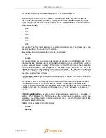
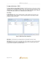
PL Scramble Code

 (Physical Layer Scrambling is available in DVB-S2X single mode)  


Description:

 This is used to specify a randomized scrambling sequence applied to each 

PL frame and initiated at the end of each PL header.  Scrambling randomizes band 
energy dispersion a

nd allows for a “signature” when may provide association to a satellite 

operator or satellite. The complex code relates to an “n” value defined by an entry of 

0 to 

262 141. 


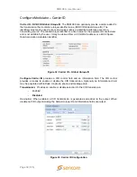
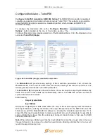
PRBS  Enable/Disable

  A  pseudo  random  binary  sequence  test  signal  is  available  for 

testing.  When  Enabled  the  PRBS  replaces  the  normal  input  modulation  feeding  the 
modulator. Select Disabled for normal output applications. 


The PRBS feature provides a digital test signal with known properties used for BERT (bit 
error rate testing) of satellite equipment or transmission paths. Test signals used are a 
binary PN (Pseudo-Noise) signal known as a PN-23 or Inverted PN-23. The test signal is 
selected in the PRBS tab.  


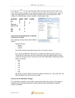
IMPORTANT: For normal or non-testing applications in which the input is to be 
used to modulate the satellite IF or L-Band carrier output, the PRBS test signal 
must be set to DISABLED. 


Summary of Contents for SMD 989

Page 1: ...January 2018 Form 8011L www sencore com 1 605 978 4600 Revision 3 2 2 SMD 989 DVB S2 Satellite Modulator User Manual...

Page 2: ...uld be made directly to those companies This document may also have links to third party web pages that are beyond the control of Sencore The presence of such links does not imply that Sencore endorse...

Page 3: ...lease RJH 10 28 2011 2 1 Updates for 2 1 Release RJH 01 17 2012 2 2 Update for 2 2 0 Release GJL 05 01 2012 2 3 Update for 2 3 0 Release GJL 01 16 2013 2 4 Update for 2 4 0 Release GJL 06 07 2013 2 5...

Page 4: ...bjects have fallen into the apparatus the apparatus has been exposed to rain or moisture does not operate normally or has been dropped Do not expose this apparatus to dripping or splashing and ensure...

Page 5: ...To reduce the risk of shock the SMD 989 must be connected to a mains socket outlet with a protective earthing connection For the SMD 989 the mains plug is the main disconnect and should remain readily...

Page 6: ...ation 19 SMD 962 Option DVB S2 S2X QPSK 8PSK Modulation 19 SMD 964 Option DVB S2 S2X 16 32 64APSK Modulation 19 SMD 965 Option 30 Msps 20 SMD 966 Option 45 Msps 20 SMD 970 Option TS Analysis 20 SMD 97...

Page 7: ...Tab 70 Controlling the SMD 989 Using the Front Panel 71 Front Panel Quick Actions Menu 71 Front Panel Modulator Settings 72 Modulator Input Configuration 72 Modulator Configuration Modulation Mode Con...

Page 8: ...age 8 105 Events 92 SNMP Trap Configurations 93 Front Panel About 93 About Software 93 About Hardware 93 Licenses 94 Appendix 95 Specifications 95 Open Source Software 102 Warranty 103 Support and Con...

Page 9: ...List with SMD 912 A 32 Figure 25 Single stream status 33 Figure 26 Multistream status 33 Figure 27 Configuration Modulator settings menu example 34 Figure 28 Modulation Mode selection SMD910 Left and...

Page 10: ...ion 62 Figure 67 SNMP communities 62 Figure 68 SNMP Managers 63 Figure 69 Alarms reporting view 64 Figure 70 Logs reporting view 64 Figure 71 Logs Severity Transition Indicators 64 Figure 72 Alarms Vi...

Page 11: ...S2X This manual describes how to install configure and operate the SMD 989 DVB S S2 S2X TurboPSK Modulator It is written for professional operators of video distribution systems and assumes a prerequi...

Page 12: ...put IP Internet Protocol ISI Intersymbol Interference LED Light Emitting Diode MAC Media Access Control Mbps 1 000 000 bits per second MER Modulation Error Ratio MPEG Refers to standards developed by...

Page 13: ...0 MHz input reference Looking at the rear of the chassis the left slot is bay 1 and the right slot is bay 2 Each bay is independently controlled and operated Therefore each bay needs to be configured...

Page 14: ...re 1 is used to provide a sample of the internal reference clock when it is desired to synchronize other equipment to the modulator s reference clock or output The output level is approximately 0 dbm...

Page 15: ...e SMD 912 or SMD 912A Module option offers a single TS stream modulation A single stream input to the modulator is selected through either the ASI or IP inputs There are two IP input ports and two ASI...

Page 16: ...r use with the SMD 920 The L band Output frequency is user settable from 950 to 2150 MHz IF OUT IF IN 1 2 3 4 DATA IN L BAND OUT MON PRI ASI IN Figure 6 SMD 920 L Band output shown with SMD 910 The SM...

Page 17: ...w 10MHz DC connector Figure 8 SMD 940 SMD 942 Option 24VDC BUC Power 10MHz on L Band The SMD 942 Option includes option SMD 940 with the additional capability to provide 24VDC power along with 10MHz...

Page 18: ...t the need to power down the unit or remove the unit from the rack Figure 10 SMD 952 Dual Redundant AC Power Supply SMD 954 Option Dual Redundant DC Power Supply The SMD 952 Option Dual Redundant DC P...

Page 19: ...s sourced from any of the ASI or IP inputs The user is allowed to select the desired amount of inputs and type from the front panel web interface and or SNMP This option can be licensed on an SMD989 u...

Page 20: ...d as a switch to backup trigger and as alarm indicators This option can be licensed on the unit at any time without sending it back to the factory SMD 971 Option BISS Scrambling The SMD 971 option is...

Page 21: ...r use the following steps 1 Locate the AC power cord included with the SMD 989 2 Plug the female end of the power cord end with no prongs into the back of the unit 3 Locate a protected outlet usually...

Page 22: ...usts on the rear of the unit will not be obstructed 2 Insert the rack mount clips into place over the mounting holes in the rack 3 Slide the SMD into position in the rack 4 Secure the SMD to the rack...

Page 23: ...for initial IP settings Upon correctly connecting to the unit a dialog box similar to Figure 14 appears asking the user to login By default the password is left blank Once logged on the password can...

Page 24: ...d icon is selected The inputs available on the SMD 912 A modulator includes 2 ASI inputs and 6 IP inputs in both IP port 1 and IP port 2 Clicking on the sign by each ASI port allows the advanced detai...

Page 25: ...ght near the right side of the listing If the port is enabled and no sync is detected an error will be indicated by a red light Errors can be user enabled disabled if desired Please see the Alarm Logs...

Page 26: ...9 Figure 19 Inputs on SMD 910 Modulator Each IP input port listing or section contains an active input bitrate indication on the right side of the section When the input is enabled and an active trans...

Page 27: ...IGMP filter information which reflects the current settings of the IP input port Each input can be configured within a configuration menu Figure 21 represents the IP settings SMD 910 for an individua...

Page 28: ...address is the IP address the source device is sending to Destination Port 0 65535 This is the UDP port the source device is sending to This is the only setting required to receive a unicast stream In...

Page 29: ...different The IP inputs available on the SMD 912 A modulator include 6 IP inputs These six inputs may be sourced from either IP port 1 or IP port 2 These six possible inputs are shown when the Show D...

Page 30: ...he settings in the input s Configure IP Receive menu The Receive Enable Disable field is used to make the input active or inactive When enabled or active the SMD 989 begins to monitor the input status...

Page 31: ...ceived by the SMD989 SSRC Filter Value 0 4294967295 The Filter Value the SMD 989 checks for before receiving a stream with RTP SSRC Buffer Mode Size KB Delay ms Allows option to set buffer mode to Siz...

Page 32: ...ation regarding the settings and status of the input Clicking on the sign by each IP port allows the advanced details to be shown as presented in Figure 24 Click on the down arrow to close the advance...

Page 33: ...verviews the processing or modulator as shown in the middle of the individual bay home screen Depending on the enabled licenses the status might look slightly different as shown in Figure 25 and Figur...

Page 34: ...of the BISS encryption to the modulator transmission PRBS Provides Psuedo Random Binary Sequence bit error rate test signal Carrier ID Provides configuration of the Carrier ID of the modulator transm...

Page 35: ...ckup can be set to On Primary TS Sync Loss On Primary TS Analysis Failure or Manual Only TS Sync Loss mode allows the SMD 989 to switch to backup if the primary input transport sync is lost In TS Anal...

Page 36: ...in the Symbol Rate field With output Symbol Rate you enter the desired output symbol rate It must be mathematically proper based upon the input bit rate measured by the system When a higher than neede...

Page 37: ...ates for DVB S DSNG and DVB S2 The remaining settings include Bold indicates default Pilot Insertion Only available in DVB S2 Modes Enable Disable Description When enabled every 16 slots of 90 symbols...

Page 38: ...tion payload rate Disabling rate adaptation is desirable where the input TS must be preserved through the transmission chain In such use cases it is expected that the input TS bitrate is fairly consis...

Page 39: ...ived from a 48 bit MAC address or a 48 bit Space Data Association modulator identifier Figure 32 Carrier ID Global Unique ID Configure Carrier ID provides a CID control field and an information field...

Page 40: ...ongitude value is not transmitted in the CID Telephone Provides an entry of a contact phone number with an extension number to the CID Information Field Value Entry Enabled Disabled Description When e...

Page 41: ...d when the number of detected Continuity Count Error per second exceeds the value entered Can be set from1 to 999 errors per second Default is 1 error per second PMT Error an error will be indicated w...

Page 42: ...Multi stream DVB S2 VCM as shown in Figure 35 allows a modulation type and FEC to be set for each stream in the modulation Each input can be set to the desired incoming stream If the input set to OFF...

Page 43: ...used are a binary PN Pseudo Noise signal known as a PN 23 or Inverted PN 23 PN23 Normal A normal version of the Pseudo Noise PN 23 test signal PN 23 Inverted An inverted version of the Pseudo Noise P...

Page 44: ...it will be altered Scrambling Enabled Disabled When set to Enabled the BISS encryption feature becomes active and is ready for the entry of either the Mode 1 or Mode E session word ID When Disabled n...

Page 45: ...he Turbo PSK parameters The Enter Rate By field provides the user a choice of how to setup the output Symbol Rate entry fields The values in these fields are mathematically related The SDM 989 contain...

Page 46: ...tral Inversion Normal Inverted Description Determines whether the spectrum is inverted or normal Note When the SMD 920 L Band option is installed the default spectral inversion is inverted as the upco...

Page 47: ...ellite applications using the TurboPSK modulation Reduced Latency Selections Disabled Default No latency reduction with additional input buffering Normal Introduces slight latency without additional i...

Page 48: ...entry of these parameters The Enter Rate By field provides the user a choice of how to setup the output Symbol Rate or Max Bitrate entry fields The values in these fields are mathematically related de...

Page 49: ...e or a symbol rate below the minimum there must be enough nulls in the input transport stream to be removed to allow the lower bitrate or symbol rate or errors in the transmission transport stream res...

Page 50: ...d DVB S2X Modes Normal 64 800 bits Short 16 200 bits Description Short frames introduce more overhead but give a shorter encapsulation delay Short frames are 4 time shorter than normal frames Spectral...

Page 51: ...frame and initiated at the end of each PL header Scrambling randomizes band energy dispersion and allows for a signature when may provide association to a satellite operator or satellite The complex...

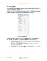
Page 52: ...here are three quick access buttons at the top of the Outputs section These buttons provide easy access to common functions or functions that may need to be accessed quickly Mute By clicking the mute...

Page 53: ...ating field is clicked the output modulation is removed and a carrier only is transmitted By clicking the up or down arrows the output RF level can be increased or decreased incrementally By clicking...

Page 54: ...input is at the proper level The Level indication can be Low OK or High If this does not show OK as the status check that the IF output is set to 10dBm If the level indicates LOW or HIGH you may incre...

Page 55: ...m specific settings to be set or modified Located directly under the admin control panel are the options for saving loading profiles changing the password downloading the SNMP MIBs downloading the dia...

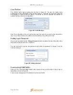
Page 56: ...from system to system to allow the profile to load If a profile is loaded onto a different channel platform the profile will not load Setting Login Password Once a user has clicked on the Change Pass...

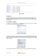
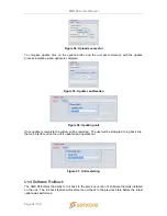
Page 57: ...unit s software click on the Update Unit button located at the top of the admin tab This will open a dialog box as shown in Figure 52 The first step is to select the update file to update by clicking...

Page 58: ...ating unit Once update is complete the system will be restarted The user will be prompted to log back into the web interface once the unit is updated and operational Figure 57 Unit restarting Unit Sof...

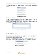
Page 59: ...on the Update License button Figure 59 Update License 10 MHz Reference Clock In the admin tab under system information the 10 MHz reference is shown This can either be internal or external The refere...

Page 60: ...of the status Clicking on the configure cog a dialog box will appear similar to Figure 62 For the modulator configuration only IP subnet and gateway are allowed to be set The management port supports...

Page 61: ...Spectral Inversion Alpha Filter Rolloff Clean Carrier CW IF Output Frequency IF Output Level IF Output Tilt RF Output Frequency L O Offset RF Output Level License Configuration The user has the abili...

Page 62: ...configured using an NTP server by entering the address to synchronize the time and date or it can be entered manually as shown in Figure 66 SNMP Communities The communities for the SNMP management can...

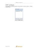
Page 63: ...SMD 989 User Manual Page 63 105 SNMP Trap Managers The managers for the SNMP management can be entered or removed by clicking on Configure SNMP Managers Figure 68 SNMP Managers...

Page 64: ...Logs click Download and a TSV file will be downloaded from the SMD 989 The TSV file can be imported to a spreadsheet or text document The Logs Severity Transition Indicators at the bottom of the Alar...

Page 65: ...f the selected alarm error condition The Error drop down menu is shown in Figure 74 Each condition can be configured as an error or information situation under log severity The Alarm Relay can also be...

Page 66: ...with the TS RTP Reception Error RTP reception errors indicated Output Buffer Error Data underflow overflow in buffer rate adaption issue where TS packets are discarded TS Continuity Count Error TS Ana...

Page 67: ...xpand the event configuration options The Selection Options popup menu allows easier configuration of the selected event Refer to Figure 77 Event Descriptions Name Description of Event 10MHz Ext Ref C...

Page 68: ...be enabled disabled from sending SNMP Traps The current status is shown under configuration To enable disable the SNMP events click on the Configure button located on the right side of the screen The...

Page 69: ...he MPEG IP Data Link is broken MPEG IP TS Sync Error Indicates MPEG IP Data interface cannot sync with the TS RTP Reception Error RTP reception errors indicated Output Buffer Error Data underflow over...

Page 70: ...equipment found within the SMD 989 platform It further provides licensing information although added information on licensing may be found in the ADMIN tab This information will be referenced when ta...

Page 71: ...d Bay 2 Press the Up or Down arrow key and the main menu will be displayed as shown to the right The user can select from the following Modulator settings for the particular bay Administrator settings...

Page 72: ...the user will be able to set input modulation and output parameters for the given bay the modulator is installed Modulator Input Configuration Once input configuration is selected all available input...

Page 73: ...y 2 listings in the Main Menu The Modulator Configuration menu has several menus which configure the modulator The menus vary with hardware and licensing options The modulation mode is selected in the...

Page 74: ...nding on the modulation mode selected Modulation Parameters Primary Input Backup Input Active Input Switch to Primary Secondary Input Configure Failover Enter Rate By Symbol Rate Max Bitate Modulation...

Page 75: ...tions which direct the modulator to return or switch back to the primary input Restore to primary options include Primary TS Sync Restored Backup TS Sync Loss Primary TS Error Manual Only Primary TS A...

Page 76: ...the input bit rate measured by the system When a higher than needed symbol rate is entered the modulator inserts null packets to achieve the rate When entering a lower than needed symbol rate the SMD...

Page 77: ...vailable in DVB S2 or DVB S2X single mode Description When enabled a rate adaption is applied When disabled the rate adaptatiois not active Rate adaptation adds or removes null packets and re stamps P...

Page 78: ...dds latency reduction to the Reduced 2 mode Minimum Adds latency reduction to the Reduced 3 mode Description The reduced latency modes of the TurboPSK modulation provides several levels of latency tha...

Page 79: ...inverted version of the Pseudo Noise PN 23 test signal When Enabled the normal input signal to the modulator is removed and replaced with the selected PN 23 or Inv PN 23 signal The PRBS signal is ena...

Page 80: ...enabled the entered phone number is added to the Information Field of the CID You may enter up to 18 digits or a total of 17 digits if an extension number is entered in the ext field When disabled th...

Page 81: ...f individual Pids within the incoming transport stream in which you do not want the TS Analysis to actively analyze This eliminates unwanted TS Analysis error logs or alarms on Pids known to contain c...

Page 82: ...sent for a period exceeding the time entered in ms Can be set from 100ms to 10000ms Default is 500ms ES PID Error 1 6 an error will be indicated when an Elementary Stream ES is not present for a perio...

Page 83: ...output is adjustable between 30 to 5 dBm The SMD 920 s optimum input level default is 10 dBm The tilt adjustment allows a user to adjust the overall slope of the output spectrum The range is selectabl...

Page 84: ...us is lost The oscillator status is an indication the oscillator is locked for confidence monitoring An alarm can be enabled to alert if the oscillator status becomes unlocked If duplexing options are...

Page 85: ...ed unit profiles to unit memory Settings Clone Enable Disable cloning of settings between bays of the modulator Reference Clock Internal or External Indicates if 10MHz reference clock is generated int...

Page 86: ...P ADDRESS 10 0 0 61 SUBNET MASK 255 255 255 0 GATEWAY 10 0 0 1 MAC 00 00 00 00 00 00 LINK STATUS HALF DUPLEX The each modulator comes standard with an IP input for data reception The physical settings...

Page 87: ...ace Temperature The current temperature for the unit can be viewed in both Centigrade and Fahrenheit Front Panel Lock The front panel can be locked to prevent any accidental changes from being made A...

Page 88: ...f the front panel holds all of status and alarm indications for the SMD 989 platform The alarms logs SNMP and relays are separated by individual menus and configurable to the exact settings a user des...

Page 89: ...with the TS RTP Reception Error RTP reception errors indicated Output Buffer Error Data underflow overflow in buffer rate adaption issue where TS packets are discarded TS Continuity Count Error TS Ana...

Page 90: ...ALARM NOTIFICATION ENABLED sensor3VMinLimit 0 3 10 VDC sensor3VMaxLimit 0 3 50 VDC 5 Volt Controller Supply sensor5VMinLimit 0 4 70 VDC sensor5VMaxLimit 0 5 30 VDC 12 Volt Controller Supply sensor12V...

Page 91: ...or Indicates MPEG IP Data interface cannot sync with the TS RTP Reception Error RTP reception errors indicated Output Buffer Error Data underflow overflow in buffer rate adaption issue where TS packet...

Page 92: ...if the user does not want it to be logged An alarm can be disabled and a SNMP trap can still be enabled to be generated for an event Name Description of Event 10MHz Ext Ref Clock Change Indicates the...

Page 93: ...IP 10 0 2 45 192 168 1 45 SNMP Trap Configurations The system s SNMP communities can be configured by selecting SNMP Trap Menu from the reporting options In the SNMP trap communities IP addresses can...

Page 94: ...VISION F L BAND UPCONVERTER LOCATION BAY 1 MODEL SMD 920 ASSEMBLY 2 NAME 1143 PI 0 LICENSE SELECT 961 DVB S DSNG MODULATION 962 DVB S2 MODULATION 963 DVB S2 MULTI STREAM MODUL 964 DVB S2 16 AND 32 APS...

Page 95: ...er LED Connector RJ45 Front Panel Indicators Input LED Green indicates valid input on selected input Off indicates no valid signal on the selected input Error LED Red indicates error is occurring OFF...

Page 96: ...Thread Size 8 32 SMD 952 Dual Redundant AC Power Supply Option Operating Voltage 95 135 VAC or 180 265 VAC Current Draw 275 Watts Frequency 47 63Hz Line Cord Detachable 3 prong Redundancy Dual Hot Swa...

Page 97: ...Stream Modulators General RoHS Compliant Yes ASI Serial TS Input Connector 2 BNC female Impedance 75 ohms Standard ETSI EN 50083 9 DVB ASI Data Bit Rate 270 Mbps Packet Size 188 or 204 byte support T...

Page 98: ...3 4 5 6 7 8 8PSK 2 3 5 6 8 9 16QAM 3 4 7 8 Min Symbol Rate 0 5 MSps Max Symbol Rate Up to 45 MSps with SMD 966 License Roll off Factor 20 25 35 Spurious Performance 50 dBc 10 dBm PRBS PN23 Inverted PN...

Page 99: ...Mbps Network Jitter Buffer 100 KB to 4MB Multistream Modes DVB S2 Single Stream CCM DVB S2 Multistream CCM DVB S2 Multistream VCM TS Supported Up to 6 any combination of ASI and IP SMD 964 DVB S2 DVB...

Page 100: ...r Detection SMD 910 or SMD 912 A TS Analysis TR101290 P1 Error Detect Adjustable Thresholds TS Analysis Inputs Dual Analysis Primary and Backup Inputs TS Analysis Thresholds User definable thresholds...

Page 101: ...ce 50 dBc 10 dBm SMD 910 Spurious Performance 58 dBc 10 dBm SMD 912 A Monitoring L Band Output Secondary Output Connector 1 SMA female Level 20 dBc Return Loss 15 dB IF Input Input Connector 1 BNC fem...

Page 102: ...L Version 2 1 Feb 1999 Johannes Erdfelt Thomas Sailer Brad Hards Lighttpd 1 4 23 BSD 2004 Jan Kneschke Linux 2 6 30 GPL Version 2 June 1991 Linus Torvalds et Al Log4cpp 1 0 GPL Version 2 1 Feb 1999 Ba...

Page 103: ...y Sencore warrants this instrument against defects from any cause except acts of God and abusive use for a period of 1 one year from date of purchase During this warranty period Sencore will correct a...

Page 104: ...by going online to www sencore com and select Support 2 Select Service and Repair from the options given 3 Fill in the following required information a First Last Name b Company c Email d Phone Number...

Page 105: ...Sencore Inc 3200 Sencore Drive Sioux Falls SD 57107 USA www sencore com Copyright 2013 Sencore Inc 1 605 978 4600...

Reviews: