4.2.3 Wire Connection
a.
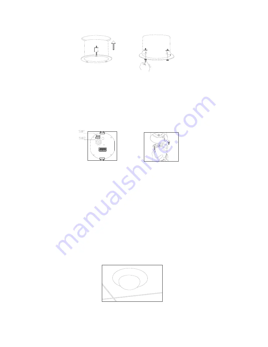
Loose the screws on the out dome cover and open the cover.
b.
Connect BNC video interface of speed dome camera with video wire (BNC). Connect the
power supply interface with the ready power supply line. Connect the RS485 interface with
the ready RS485 control line. Then replace the cover after examination.
Notice:
Do not connect positive and negative polarity of RS485 contrarily (A: RS485 positive,
B: RS 485 negative polarity). If RS485 is connected contrarily, cannot be controlled.
4.2.4 Core Mounting
a.
Set the DIP switches for SW1 and SW2 on the bottom of the dome drive for the appropriate
receiver address.
b.
Line up the green and red tabs with the green and the red labels. Push in on the tabs. Insert
the side with the green tab, then the side with red tab. Continue pushing on the ends of the
tabs until both sides click into the place.
4.2.5 Electricity
a.
Apply the power after checking the wire connection and polarity of the plug and outlet.
b.
Domes enter self-inspection, and carry out a default program when first powered on, making
a horizontal 360°and tilt 90 °rotation. After the dome stops completely, the self-inspection is
completed and dome is ready to be controlled.
4.2.6 Dome Mounting
a.
Use soft cloth to wipe off dust and smudges of transparent dome, avoid scratching the
dome.
b.
Push the doom into the case, aim at the ceiling hole, and then turn the dome in the same
direction clockwise in order to connect the dome with the ceiling surface closely.
17


