


DU/SD SERIES INSTALL OPERATION MAINTENANCE MANUAL
|
25
COMMISSIONING INFORMATION
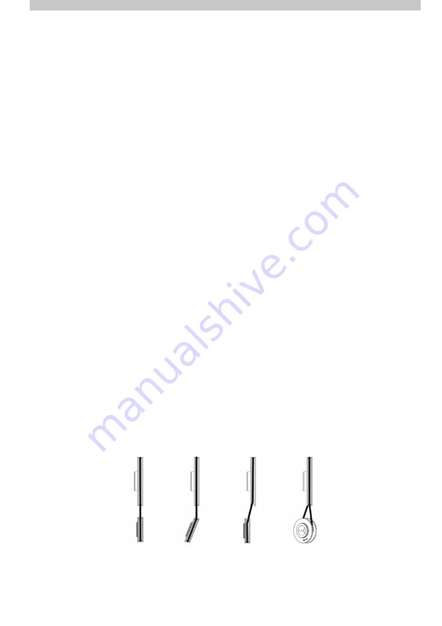
Correct
Alignment
Horizontal
Angularity
Axial
Offset
Vertical
Angularity
AMI084-A
Figure 20: Pulley Alignment
4.0 COMMISSIONING
Prior to commencement ensure Main Isolator Switch is OFF and correct electrical Lock Out Tag Out (LOTO)
procedures are followed.
Failure to do so may result in Injury or Death.
A commissioning report template is available in Appendix D of this document. AS5601.1 Appendix O provides additional
guidelines for commissioning.
WARNING! This unit is fitted with an auto fan switch. If temperatures within the unit match the overtemp set
temperature the blower fan will start without warning. Electrical isolation of the unit is the only way to prevent
this from occurring.
4.1 UNIT DETAILS
1. Record unit details on the Commissioning Sheet including Model Number and Serial number which can be found
on the control box.
2. A copy of the commissioning document should be kept inside the document pocket.
4.2 GENERAL INSTALLATION CHECK
1.
Confirm that safe access is available to unit. If the unit is located on a roof, ensure that a certified anchoring system
is installed and that the appropriate harness is available for use during commissioning.
2.
Confirm the weatherproof casing is in good condition and free from damage.
3.
Check that the unit is sufficiently secured and level. If located on a roof stand, ensure that the roof stand is installed
as per the designing engineers’ specifications.
4.
Check that ductwork from the unit is correctly installed and secured by a qualified person.
5. Flue installed and secure.
6. Check that all pads are in position and free of foreign material.
4.3 ELECTRICAL CHECKS
4.3.1 Electrical Installation Checks
1. Turn OFF main isolator and follow LOTO procedures.
2. The electrical connections are to be completed by a licensed and experienced person.
3.
Check that the isolator is fitted and operational. If the isolator is damaged the unit must not be commissioned or
operated until the issue is resolved.
4. Check that all wiring is secure and terminated. All cable protection is in good condition.
5. Check that the single/3 phase power is connected to the unit. Test supply connection and record voltage.
6.
Confirm that the thermostat is connected and operational. Refer to Section 4.5 for further details
4.3.2 Blower Box Checks
1.
Check the fan motor is securely fitted and aligned. The motor should be sitting level. Confirm that the motor
platform is properly secured and tighten if necessary.
2.
Check that pulleys are correctly aligned. Confirm horizontal and vertical angularity as well as axial offset are not
present. Confirm that all taper locks are secured.
CORRECT
ALIGNMENT
HORIZONTAL
ANGULARITY
AXIAL
OFFSET
VERTICAL
ANGULARITY


