background image


29 


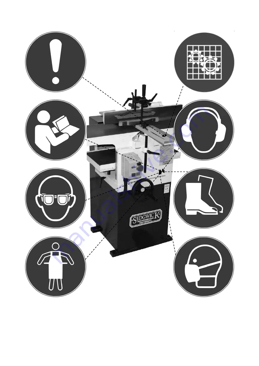
General caution 


Check guard 


Refer to instruction manual


Use hearing protection


Use protective eyewear 


Use protective footwear


Use protective apron 


Wear a mask


All notices and labels which are affixed to the machine must be kept readable and may 
not  be  removed.  Any  that  have  become  damaged  or  unreadable  must  be  replaced 
promptly.


Summary of Contents for PT255

Page 1: ...KEEP SAFE FOR FUTURE USE PT255 PLANER THICKNESSER OPERATION AND MAINTENANCE INSTRUCTIONS Designed Manufactured in the U K MACHINE SERIAL NO ...

Page 2: ...2012 Place of Declaration M Sedgwick Co Ltd Date of Declaration 09 May 2017 Name Address and ID No of Notified Body TUV SUD BABT Octagon House Concorde Way Segensworth North Fareham PO15 5RL NB 0168 No of EC Type Examination Certificate MAC000012 i01 Declaration I declare that the machinery fulfils all the relevant provisions of the following Directives Machinery Directive 2006 42 EC Electromagnet...

Page 3: ... Fingers 7 0 The Cutterblock 7 1 Replacing the planer knives 7 2 Optional Monobloc with Tersa Cutters 8 0 Preparations for machining 8 1 Pilot Checks 9 0 Surface Planing 9 1 Flatting 9 2 Planing Wide Boards 9 3 Planing Bowed Boards 9 4 Edge Planing Squaring 9 5 Bevelling or Chamfering 9 6 Push Blocks and Push Sticks 10 0 Thicknessing 11 0 Diagnosing Faults in Planing 12 0 Limitations of Use and Sa...

Page 4: ... damages resulting from a failure to follow the instructions set out in this manual Should you have any questions on this manual please contact the manufacturer Design and Purpose The PT Planer Thicknesser is a dual purpose machine designed to plane wood and similar materials by means of a horizontally rotating cutterblock When surfacing the workpiece is passed over the top of the cutterblock and ...

Page 5: ...ALL HANDLE CUTTERBLOCK GUARD HORIZONTAL LOCK 4 CUTTERBLOCK GUARD VERTICAL LOCK THICKNESSING TABLE RISE AND FALL THICKNESSING TABLE VERTICAL LOCK MOTOR SWITCHGEAR REAR MACHINE GUARD REAR CUTTERBLOCK GUARD FENCE LATERAL LOCK OPTIONAL FOOT OPERATED STOP SWITCH ...

Page 6: ... DIAMETER 40 mm FEED SPEEDS 5 5 m min FENCE SIZE 550 x 90 mm TILTING ANGLE OF FENCE 0O 45O CHIP EXTRACTION OUTLET DIA 125mm VOLTAGE FREQUENCY 3 PHASE EARTH 400 230 V 50 60 Hz 1 PHASE N EARTH 230V 50 60 Hz MOTOR RATING 1 5Kw MOTOR FULL LOAD CURRENT IN AMPS 3 PH 3 6A 1 PH 9 0A STARTING CURRENT IN AMPS 3 PH 21 6A ph 1 PH 56 0A REQUIRED FUSE SIZE IN AMPS 3 PH 16A ph 1 PH 25A REQUIRED CABLE SIZE 3 PH 2...

Page 7: ...ve clothing wear tear resistant sturdy overalls Use of protective footwear wear safety shoes with protective toes and sturdy grips which are also penetration resistant Gloves avoid wearing gloves when operating the machine to avoid the gloves getting caught Hair persons with long hair should tie their hair up and wear a hairnet to avoid the risk of hair being tangled on the machine and Ears wear h...

Page 8: ...proper training in the handling of heavy machinery There is a risk of physical injury when moving the machine The machine could be damaged or written off if not handled properly during transportation The machine dimensions and weights are as follows DIMENSIONS Length x Width x Height 1400 x 800 x 1160 MACHINE WEIGHT Total Weight including Packing Crate 170 Kg 262 Kg Always use a sling or hoisting ...

Page 9: ...d be clear and unobstructed space to enable the work being done at the machine to be done without risk of injury to operators Consider the position of the machine with regard to other fixed equipment and walls The chosen floor space on which to site the machine should be in good and level condition to enable the machine to be anchored at four points and should be free from material e g chips Holes...

Page 10: ...achine outdoors Ensure the environment for operating woodworking machinery is kept clean and tidy and damp free Only operate the machine in ambient temperatures Remove the protective grease using turpentine or paraffin Do not use any solvent petrol or gas oil which might dull or oxidise the paintwork Lightly oil cleaned surfaces to prevent rusting 435mm 345 mm ...

Page 11: ...ed as hazardous waste and disposed of safely in accordance with environmental laws 3 0 Connection to a Dust Extraction System Exposure to dust can damage lung health and this machine must be connected to a compatible dust extraction unit using a suitable size and grade of vacuum hose before operation Wood dust can be harmful to health by inhalation and skin contact and concentrations of small dust...

Page 12: ...these directions when connecting to the mains The motor and control gear have been wired in at the factory and tested before despatch Do not open the switch box on the machine without the written consent of the manufacturer Violating this stipulation could invalidate the machine s warranty All that is required is to connect the power supply to the starter from your isolator First check that the su...

Page 13: ...f switch on Allowed variation minus 6 Check that correct cable size has been used to install the machine Change if necessary Long runs of cable can cause voltage drop Check that voltage is not outside the minus 6 tolerance Re site the machine nearer supply or increase the cable size to compensate It is possible for 3 phase machines to operate with only 2 phases of the supply This will create an ov...

Page 14: ...e direction Carry out a functional test of this button works after installation and prior to first machining 5 3 Circuit Protection In case of a mains failure the starter is fitted with no volt release protection and will not restart without being switched on again On restart always ensure that the brake is released The starter is also fitted with an overload protection device An electrical overlo...

Page 15: ...er the axis of the cutterblock This guard should be maintained through regular cleaning and lubrication and if it becomes distorted through misuse then it should be replaced 6 2 The Rear Cutterblock Guard To the rear of the fence a hinged guard is mounted which is known as the rear cutterblock guard This is designed to guard that part of the cutterblock that is on the side of the fence remote from...

Page 16: ...at the mains It is not sufficient just to shut off power at the machine Next put up a notice saying cutters being changed in case you have to leave the machine for any reason and someone else might try to use it not knowing the knives are loose Clean off any chippings and dust from the machine tables and move the fence and front cutterblock guard out of the way Points to check on the cutterblock a...

Page 17: ...er it is bowed or twisted and the positions of defects such as knots wavy edges etc He should also consider any other peculiar characteristics of the material such as salicaceous or calceous deposits which could cause severe blunting and chipping of the cutters If a number of abrasive pieces are to be planed use the ends of the cutter rather than the middle if possible 8 1 Pilot Checks Details on ...

Page 18: ... fed in with consideration to the grain direction The following illustration shows how timber fed through the cutters against the grain will cause it to tear out producing a ragged finish Always feed with the grain running down towards the front of the table when in the planing mode and the opposite when thicknessing Correct Incorrect Feed Feed Slope of grain Slope of grain 9 1 Flatting Workpiece ...

Page 19: ...ence in order to maintain adequate control In this event the wood should be fed up and over the cutters by means of a push block as described in the relevant section of this manual Small pieces are the most difficult to control so consider do you really need to face and edge them The HSE has published guidelines on the ergonomically correct use of hand fed planers some of which is reproduced here ...

Page 20: ...ce as illustrated in positions 1 and 2 9 2 Planing Wide Boards Wide boards should be fed at an angle to reduce initial impact and the risk of throwback Fence 10mm max Wide board Bridge Guard 9 3 Planing Bowed Boards Slightly bowed boards may be planed by the method shown below but care must be taken to ensure two point contact on the infeed table to avoid throwback Badly bowed boards should not be...

Page 21: ...idge guard and the fence The bridge guard should be adjusted both horizontally and vertically to leave only 10mm from both the feed table and the workpiece as shown below 10mm Bridge Guard 10mm When edge planing follow these guidelines regarding the correct positioning of hands Preparatory Place the workpiece against the fence and move it with the right hand forward to about the front edge of the ...

Page 22: ... due to the abrasive nature of the glue line For this reason when edge planing keep well over to the far side of the cutter leaving the rest of the cutter for other work Plywood chipboard and the like are best cut on a dimension saw using a tungsten tipped blade which gives an excellent finish Another alternative is to place the material on a vertical spindle moulder using tungsten tipped cutters ...

Page 23: ...rupt contact with the cutters that a throwback will be almost inevitable Alternatively consider planing a longer piece of timber and cutting off the required length Handle doweled and glued to pushstick therefore no metal contact possible with the cutters Hardwood strip housed and glued to body of pushblock Narrow pushblock for short narrow thin material Abrasive paper glued to base to give better...

Page 24: ...hese marks are then removed by the cutting of the planer knives At the back of the cutterblock is a smooth metal roller A flat belt powers both rollers through a gear reduction mechanism and each roller is spring loaded to accommodate variations in wood thickness These roller springs are adjustable to enable you to vary the degree of pressure that they exert For further details see Maintenance For...

Page 25: ...rwise smooth finish Chipped cutter Replace the cutters The timber drops at the end of the cut and gouges out the end of the timber The knives are too high above the cutterblock Re set the cutters Excessive vibration causing a poor finish Unbalanced cutters or block Check the balance of the cutters on a balancing stand and grind the heavier one so as to balance correctly Run the block without cutte...

Page 26: ...ntial that all operators of planer thicknesser machines are adequately trained in the use adjustment and operation of the machine this covers in particular The dangers associated with the operation of the machine The principles of machine operation correct use and adjustment of the fence jigs and safeguards The safe handling of the workpiece when cutting The position of the hands relative to the c...

Page 27: ...s roughly in proportion to the width of cut Blade Sharpness Dull and worn blades exert more force on the timber thus creating more noise Balance Out of balance blades mean vibration and changes in cutting conditions resulting in increased noise levels Extraction Air Velocity System Design Resonant conditions can lead to high noise levels excessive turbulence and chip impact can increase noise leve...

Page 28: ... BEFORE OPERATING THIS MACHINE ENSURE THAT 1 All guards and fences are securely fitted and correctly set in accordance with the current regulations 2 Tooling is of the correct type sharpness and direction of cut and is securely fastened 3 Correct spindle speed and feed is selected for the cutter equipment where appropriate 4 Loose clothing is either removed or fastened and jewellery removed 5 Suit...

Page 29: ...aring protection Use protective eyewear Use protective footwear Use protective apron Wear a mask All notices and labels which are affixed to the machine must be kept readable and may not be removed Any that have become damaged or unreadable must be replaced promptly ...

Page 30: ...ife maximum reliability and optimum performance the following monthly maintenance and lubrication schedule should be carried out otherwise the machines warranty could be invalidated Improper maintenance can cause serious injury or damage For this reason it should only be carried out by authorised trained personnel who are familiar with how to operate the machine and taking into account all safety ...

Page 31: ...uld be checked for wear burrs and any play in the bearings that the arbor rides in First check the cutterblock the chipbreakers and the cutterblock screws for dirt burrs or raised nicks Slight imperfections can be removed carefully with a fine cut file The cutterblock bearings are sealed for life and require no lubrication To check their condition turn the block by hand while feeling for any rough...

Page 32: ...aight edge across the faces of the two pulleys If necessary adjust the motor pulley by loosening the allen screw locking the pulley onto the shaft If you cannot get the pulleys to align it may be because the shafts are not in line Loosen the motor mounting bolts and shift the motor until you get the required results Position the pulley as near as possible to the motor bearing If it is set too far ...

Page 33: ... setting piece The height of the roller should be set equally at both ends Use the same technique to set the plain roller to 2mm below the cutting circle The pressure springs are mounted on studs and tensioned by 13mm locknuts The pressure on each spring is factory set On the chain side of both rollers the spring should measure 65mm while on the non drive side of the rollers the springs should mea...

Page 34: ...0 in Next check both tables as a unit Check next to the fence and on the opposite side and then check the diagonals for twist Ideally the tables should be less than 0 010 in out of parallel end to end Should you find that adjustment is necessary begin by removing the infeed table sometimes dirt between the slideways can build up and cause alignment problems Clean all surfaces and lubricate with a ...

Page 35: ...e el ly y h ho ot t i it t i is s l li ik ke el ly y t to o b be e c ca au us se ed d b by y t th he e b br ra ak ke e n no ot t r re el le ea as si in ng g T Th hi is s i is s p pr ro ob ba ab bl ly y a as s a a r re es su ul lt t o of f o on ne e o of f t th he e f fa ac ct to or rs s b be el lo ow w Brake air gap setting incorrect Poor rectifier supply connection Use with phase converter Dust w...

Page 36: ...36 14 0 PT255 Planer Thicknesser Parts Diagram ...

Page 37: ...R 9054 BEARING COVER FRONT 9055 BEARING COVER REAR 9056 CUTTERBLOCK PULLEY 9057 FEED ROLLER FLUTED 9058 FEED ROLLER PLAIN 9059 FEED ROLLER BEARING THRU 9060 FEED ROLLER BEARING BLIND 9061 CHAIN SPROCKET 9062 SPRING STUD 9064 STRETCHER BAR 9065 RISE AND FALL NUT 9070 OUTFEED TABLE 9071 ANTI KICK SHAFT 9072 ANTI KICK FINGERS 9073 ANTI KICK SPACERS 9074 INFEED TABLE 9075 TABLE RETAINING PLATES 9076 R...

Page 38: ... 3SE0021 PT 1 STARTER 10 12A 3SE0006 PT 3 STARTER 4 6A Use only original spare parts supplied by the manufacturer The use of unauthorised counterfeit or inferior parts may result in damage or malfunction ...

Page 39: ...39 ...

Page 40: ...40 ...

Reviews: