Secutron MMX-2003-12NDS User Manual Download Page 18

 MMX

TM

 User Guide

15

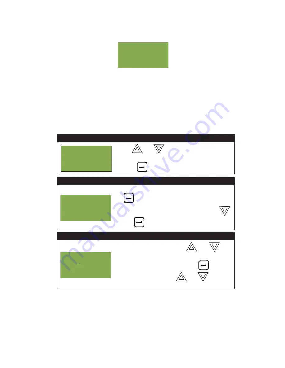
For example, if you select loop two, the screen will appear as follows:

• The first and second lines pinpoint the exact device.
• The 

current level 

is a point of reference number that is helpful to our technicians.

• The

 percent alarm

 shows how close the device is to going into alarm: 0% is the least likely, and 80% is the 

most likely.

Verified Counts

This option reports on any pre-alarmed devices that are set to verification mode. This report lists each time a 
device pre-alarms. If no devices are set to verification mode, then no report will display.

Step 1: Select Verified Counts

1. Use 

 and 

 to scroll the cursor to “Verif 

Counts”.

2. Press  

to 

continue.

Step 2: Print or View the Verified Counts

• To print the Verified Counts to the printer, press 

 when the cursor flashes beside “Printer”. 

•To print the Verified Counts to the screen, press 


then 

 when the cursor flashes beside “Screen”.

Step 3: Select loop number

•Select a loop number by using 

  and 

 to 

scroll through the numbers, or 

•Select all loop numbers by pressing 

 and 

waiting five seconds. Use 

 and 

 to scroll 

the cursor through the loops.

Loop  2    Address   001
Low  Profile  ION   Det
Current   level:   846
Percent   alarm: 0%

  -  Reports  Menu  -
2  Event  Log
3  Current  Levels
4  Verif   Count

^

^

    -  Report   to   -
1  Printer
2  Screen

-Select  Loop  Number-
Loop:  A  L  L

Summary of Contents for MMX-2003-12NDS

Page 1: ...Intelligent Fire Alarm Network User Guide MMX TM LT 893SEC Rev 1 May 2017...

Page 2: ......

Page 3: ...ode 34 5 Set Time 35 6 Clear Event Log 36 7 Clear Verification Counter 37 8 Network Restart 38 9 Configuration Info 38 10 Choose Configuration 39 Paging Operation 40 QMP 5101N and QMP 5101NV Network M...

Page 4: ...Fire Alarm and Audio system which includes MMX 2003 12NDS MMX 2003 12NXTDS MMX 2009 12NDS and MMX 2017 12NDS Using the instructions provided in this manual you will be able to Print reports Bypass de...

Page 5: ...ntrols and indicators for Alarm Supervisory Trouble and Building Indicators for AC On CPU Fault and Ground Fault Controls Indicators for Signal Silence Visual Indicator Test System Reset Fire Drill Tw...

Page 6: ...face of the panel Paper labels allow for easy English French selection and custom printed zone information Note The Acknowledge LED and pushbutton are active only on a system configured for Two Stage...

Page 7: ...y LED flashes amber when there is a supervisory alarm in the panel resulting from any latching or non latching supervisory circuit The LED turns OFF if all non latching supervisory circuits are restor...

Page 8: ...neral Alarm Timer is cancelled by the activation of the Acknowledge or Signal Silence buttons If the Auto General Alarm Timer times out and puts the panel into General Alarm the Acknowledge LED turns...

Page 9: ...ons up previous down next right and left allow you to select items on the LCD display The up and down buttons scroll through lists in a continuous loop Enter Button Use this button to select a display...

Page 10: ...ssing and holding the Lamp Test button causes all front panel indicators to illuminate and sounds the buzzer steadily Bi coloured LEDs will illuminate twice to show both colors If lamp test is active...

Page 11: ...address es of the configured slaves does not match Slave Configuration Type Mismatch This message displays if the physical loop adder does not match the loop adder type specified in the configuration...

Page 12: ...igurator Once all the Nodes have been downloaded connect the network and select the Network Restart see page 31 at the CACF Central Alarm and Control Facilities or main node If there is an alarm super...

Page 13: ...ear Verification Count 2 Config Network Reset 2 Manual Enable 0 Note You can change these access levels via the MMXTM Configurator MSW 025 MGC Net w or k Fi r e Al ar m Cont r ol Panel Nor mal C ondit...

Page 14: ...rm an audible walktest See page 26 Silent Test Perform a silent walktest See page 27 Assisted if configured Assisted walktest for large systems See page 29 4 Day night mode N A Select day or night mod...

Page 15: ...ter output must be enabled via the Configurator Step 1 Select the Reports Menu 1 Use and to scroll the cursor to Reports 2 Press to select the Reports Menu Step 2 Enter your passcode if required Enter...

Page 16: ...earliest The maximum number of recorded event log entries is 2000 Once the system reaches 2000 entries any new entry will cause 1000 of the oldest entries to be deleted At this point the display will...

Page 17: ...o navigate the Event Log Step 1 Select Current Levels 1 Use and to scroll the cursor to Current Levels 2 Press to select the Current Levels submenu Step 2 Print or View the Current Levels To print the...

Page 18: ...n no report will display Step 1 Select Verified Counts 1 Use and to scroll the cursor to Verif Counts 2 Press to continue Step 2 Print or View the Verified Counts To print the Verified Counts to the p...

Page 19: ...int Report 2 Press to continue Step 2 Print or View the Maintenance Report To print the Maintenance Report to the printer press when the cursor flashes beside Printer To print the Maintenance Report t...

Page 20: ...Step 1 Select Current Levels 1 Use and to scroll the cursor to Cur rent PWs 2 Press to select the Current PWs submenu Step 2 Print or View Current Levels To print the Current Levels report to the pri...

Page 21: ...of the information displayed on screen The first and second line pinpoint the exact device Step 1 Select Obscuration 1 Use and to scroll the cursor to Obscuration 2 Press to select the Obscuration su...

Page 22: ...n screen The first and second line pinpoint the exact device Below that is the present obscuration percentage of the device Step 1 Select CO Maint 1 Use and to scroll the cursor to CO Maint 2 Press to...

Page 23: ...The first and second line pinpoint the exact CO device which needs to be replaced The other report will say No CO Devices to report Step 1 Select Battery Voltage 1 Use and to scroll the cursor to Bat...

Page 24: ...Step 4 Pwr Src Report The battery voltage will be displayed as per this example Step 1 Select the Bypass Menu 1 Use and to scroll the cursor to Bypass 2 Press to select the Bypass Menu Step 2 Enter y...

Page 25: ...Bypass Menu Step 1 Select Device Circuit Press when the cursor is flashing beside Device Circuit to select a device Step 2 Enter your passcode Enter your passcode See page 10 for instructions on ente...

Page 26: ...n it will return to the Command Menu Input Zone Bypass Use this option if you want to bypass an entire zone of addressable devices from the panel Usually this is done during building maintenance To un...

Page 27: ...into alarm while it was bypassed you will see the following message If you select yes to unbypass this loop the system will immediately go into alarm To avoid this problem press the System Reset butt...

Page 28: ...1 Select the Walk Test Menu 1 Use and to scroll the cursor to Walktest 2 Press to select the Walk Test Menu Step 2 Enter your passcode if required Enter your passcode See page 10 for instructions on...

Page 29: ...dible Test Step 2 Select duration of Walk Test 1 The default duration of Walk Test is 6 hours To choose another time duration use the and to scroll the cursor to the desired duration time Valid range...

Page 30: ...1 Use and to scroll the cursor to Silent Test 2 Press The test will now begin Step 2 Select duration of Walk Test 1 The default duration of Walk Test is 6 hours To choose another time duration use th...

Page 31: ...lk Test trouble events D number of duplicate alarm and trouble events R number of remaining alarm and trouble events from the Walk Test list Step 5 Device View During the Walk Test During the Walk Tes...

Page 32: ...er your passcode if required Enter your passcode See page 10 for instructions on entering passcodes Step 3 Select the Assisted Walk Test option 1 Use and to scroll the cursor through the menu 2 Press...

Page 33: ...nts from the Walk Test list Press to exit and return to the Command Menu Step 5 Walk Test Device Screen Device display will be as shown A total number of alarm events for the device T total number of...

Page 34: ...nts for the device Step 1 Select the Walk Test Menu 1 Use and to scroll the cursor to Walktest 2 Press to select the Walk Test Menu Step 2 Enter your passcode if required Enter your passcode See page...

Page 35: ...L 2 Input 103 first node Adr 101 A 0 T 0 Nd 17 CPU 1 L 3 virtual coptir 101 on qla Adr 104 A 1 T 0 Nd 17 CPU 0 L 2 Input 104 first node Adr 106 A 1 T 0 Nd 17 CPU 0 L 2 input 106 first node Adr 107 A 2...

Page 36: ...outlined above Selecting manual control enable using a key switch You can set up the MMXTM to require the activation of a key switch instead of a passcode to enable manual control Once the key switch...

Page 37: ...led and then it will return to the Command Menu Step 1 Select Day Night Mode 1 Use and to scroll the cursor to Day Night mode 2 Press to continue Step 2 Enter your passcode if required Enter your pass...

Page 38: ...to Set Time 3 Press when the cursor flashes beside Set Time to select the Set Time option Step 2 Enter your passcode if required Enter your passcode See page 10 for instructions on entering passcodes...

Page 39: ...Step 2 Enter your passcode if required Enter your passcode See page 10 for instructions on entering passcodes Step 3 Select the log to clear Use and to select the log you would like to clear Use and t...

Page 40: ...d then it will return to the Command Menu If you selected no the display shows the message Operation cancelled then it will return to the Command Menu Step 1 Select Clear Verification Counter 1 Use an...

Page 41: ...ormation regarding the configuration in the system The MMXTM display will show the following while in Configuration Info mode Step 1 Select Network Restart 1 Use and to scroll the cursor to Network Re...

Page 42: ...hoose Configuration 1 Use and to scroll the cursor to Choose Config 2 Press to continue Step 2 Enter your passcode if required Enter your passcode See page 10 for instructions on entering passcodes St...

Page 43: ...that the All Call function is active This LED will not function if the DIP switch SW1 5 is set to ON Mic Active LED Flashes green to indicate any activity on the paging bus i e other microphone in us...

Page 44: ...den paging to occur All Call Button Selects all zones for voice paging This button will not function if DIP switch SW1 5 Automatic All Call is set to ON All Call Minus Button Inverts the selection of...

Page 45: ...T 5302 Paging Selector Panel LEDs Page LED Illuminates green if the zone is selected for voice paging Trouble LED Flashes amber to indicate that the zone is in trouble QAZT 5302 Pushbuttons Page Butto...

Page 46: ...and two LEDs per zone The lower amber LED indicates zone trouble The upper green LED indicates whether that zone is selected for telephone communication Telephone zone selection buttons toggle ON and...

Page 47: ...D will illuminate when there is a connection between the designated Master Telephone at the CACF and the present QMT 5302N telephone QMT 5302N Master Telephone Pushbutton Controls Call Control Pressin...

Page 48: ...lectronic magnetic optical chemical manual or otherwise without the prior consent of Secutron Canada 25 Interchange Way Vaughan ON L4K 5W3 Tel 888 SECUTRON 905 695 3545 Fax 905 660 4113 U S A 4575 Wit...

Reviews: