background image

USER MANUAL 


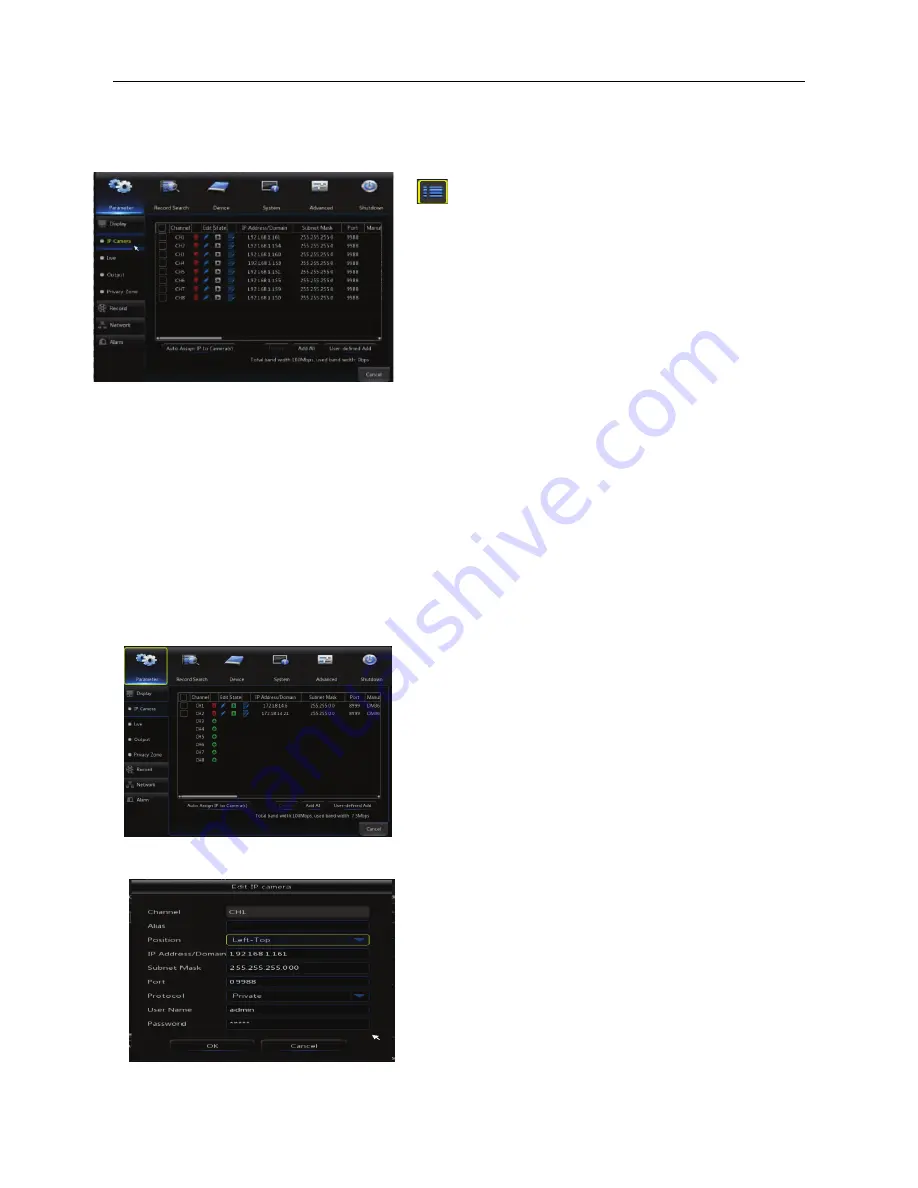
Main Menu


Picture 4-2 

PARAMETER 

Shows sub-menus for Display, Record, Network, and Alarm setup. 
 

IP Camera 

“Main Menu”

→“

Display”

→“

IP Camera” to enter into the top left menu 


Picture 4-4 

In


LIVE mode, left click the mouse button on the 

[

] icon on the toolbar, or use the [Menu] 

button on the remote control to enter the main 
menu screen, as shown in Picture 4-2. 
If system interface is locked, refer to section 4.3 
to unlock it  by inputting your  password.  By 
default, there is no password required. 

In  the  Main Menu mode, you can adjust the 

settings for Parameter, Record Search, Device, 

System, Advanced, and Shutdown. 


Channel

IPC camera channel 


To Edit

Click on the blue pencil icon to make changes 

to a camera’s network settings (bottom left menu) 


State: 

A green arrow indicates that a camera is live 


IP address: 

The


IP address of a camera, including the 

gateway 


IP Address/Domain

Shows the current IP address 

being used by a camera 


Subnet Mask: 

Displays the


current


subnet mask used 

by a camera 


Port

Displays the


current


port number used by a 

camera 


Manufacturer

 & 

Device type

Displays on screen if 

broadcast by the camera 


Protocol

  The current protocol being used 


MAC Address

The physical address for the camera.   

This is a unique identifier that stays with a camera 
since its date of production. 


Summary of Contents for SLD310

Page 1: ...1 Hi Definition 1080P NVR Network Video Recorder SLD310 4 Channel SLD311 8 Channel SLD312 16 Channel User s Manual Security Labs Inc Customer Support 800 774 0284 www security labs com V103015NVR ...

Page 2: ...EM INITIALIZATION 3 STARTUP WIZARD 3 THE NVR S MENUS 6 MAIN MENU GUIDE 7 MAIN MENU 8 PARAMETER 8 IP Camera 8 Live 9 Output 9 Image Control 10 Privacy Zone 10 Record 11 Schedule 11 Mainstream Substream Mobilestream 12 Alarm 13 Motion Detection 13 Alarm I O Input Output 14 Record Search 15 Event Search 16 Backup 16 Device 19 HDD 19 Cloud Storage 19 System 20 General 20 DST 20 NTP 21 Users 21 Info 22...

Page 3: ...e 26 E mail 27 DDNS 27 Quick Reference QR Code or P2P 29 Connecting with a desktop or laptop web browser 30 ActiveX IE Plug ins Download and Installation 30 Web Application Manager Login 30 Live Interface 31 Menu Bar 31 Live Display 31 Video Control 32 Playback 33 Record Search 33 Playback Control 34 Remote Settings 35 Local Setting 36 Logout 36 ...

Page 4: ...ound If any unusual smells or sounds are detected unplug the power cable and contact technical service at 1 800 774 0284 7 Do not remove the case cover No user serviceable parts are inside Please contact technical service for assistance in upgrading or replacing the hard drive 9 Although rarely required when replacing the clock back up lithium battery use the same part number included with the uni...

Page 5: ...l select CH1 CH2 CH3 CH4 Select a channel to view full screen 5 QUAD On Live or Playback mode switch to Quad display 6 REC Press the button to start manual record 7 MENU ESC Enter into Main menu exit or stop playing 8 Down Key Move down 9 SEL EDIT Enter into shortcut menu and select ENTER and EDIT 10 Up Key Move up 11 PTZ PTZ Enter into PTZ control interface 12 REW Move to left Rewind function dec...

Page 6: ...r stereo system 8 WAN Port Network connection to router with included LAN patch cable 9 Camera Inputs Power to POE cameras and input for video from cameras Table 1 2 Remote Control Table 2 3 Key functions of the remote control Item Key title Key function 1 1 8 Channel select 1 8 Numeric buttons 2 9 0 Numeric buttons 3 ALL Multiple display mode 4 Menu Enter into Main menu Exit 5 Up arrow Volume adj...

Page 7: ...enus and setup your new NVR Cameras can be connected directly to the RJ45 POE ports on the back of the NVR Power Supply Connection Please connect the included 48 VDC power adapter 4 8 Channel or AC cord 16 channel to the back of the unit NVR Boot up System Initialization Upon pressing the power button you will see the Security Labs logo and Customer Support contact information This same screen wil...

Page 8: ... any other compatible cameras that were discovered on your local network via the LAN patch cable connected to your router You can edit the address add or delete a camera on this list TIP Use the Auto Assign IP to camera s button to refresh any previously deleted cameras or to add newly installed cameras to the list IPC Setup Record Schedule gives you a quick way to set up the days times and type o...

Page 9: ... drive You can also select Auto overwrite for the drive to overwrite the oldest file when full select the number of days you wish to store at any time or stop recording when full Auto is the default selection and most popular choice When installing a new hard drive click the Format HDD button TIP The hard drive included with this NVR has been formatted and is ready to record ...

Page 10: ...hapter is dedicated to explaining the menu system and the manual adjustment tools that are available Popup Menu Using the mouse right click on the screen or hover the mouse pointer near the bottom of the screen to activate the Popup Menu ...

Page 11: ...utput Mainstream Schedule DDNS HDD Cloud Shutdown Main Menu Privacy Zone IP Camera Parameter Network Record Alarm Record Search Event Search Device General Users Info Log Substream Record Email Network Alarm Motion Maintain Advanced Events Record Search ...

Page 12: ...s for Parameter Record Search Device System Advanced and Shutdown Channel IPC camera channel To Edit Click on the blue pencil icon to make changes to a camera s network settings bottom left menu State A green arrow indicates that a camera is live IP address The IP address of a camera including the gateway IP Address Domain Shows the current IP address being used by a camera Subnet Mask Displays th...

Page 13: ...sequential view to be shown 5 to 300 seconds VGA HDMI Resolution VGA output or HDMI output Including 1024 768 1280 1024 1440 900 1280 720 1920 1080 Choose the best option that works with your monitor Transparency Adjusts the visibility of the menus in a range of 0 128 Channel Select the channel you wish to edit Show Time Channel Name Check these boxes if you want these items to be displayed Date F...

Page 14: ...foreground objects with a bright background i e An interior view of an object sitting near a large window 4 3D Noise Reduction Softens grain in video caused by extreme low lighting 5 WDR Wide Dynamic Range increases sensitivity to low light conditions and and enhances the back lighting function 6 AGC Automatic Gain Control governs the cameras reaction to changes in lighting Privacy Zone Privacy Zo...

Page 15: ...sable the recording function for the selected channel Stream Mode Select Mainstream or Substream Mainstream displays a higher quality picture Substream uses less processor capacity for more fluent motion of fast moving objects and consumes less hard drive space Pre Record Use this feature to store and add video activity before an alarm or motion trigger See what causes a trigger before it happens ...

Page 16: ...when needed The overall logic is that there is a maximum amount of information that can be processed per second by any NVR or DVR Allocating the resources available to each channel or camera allows you to customize your installation to achieve the best overall results Picture 4 12 Channel Select a channel to modify Resolution Set the resolution available for each camera using the drop list FPS Fra...

Page 17: ...el is selected as the one being set up shown in the top box TIP To quickly disable motion detection for a certain camera channel use the Disable Enable function The other settings for that channel will remain intact AREA SETUP Click on the Setup button to display the 20 x 15 grid pattern below The grid will overlay your camera s view for the channel being edited Use the mouse to left click a squar...

Page 18: ...s can be selected for the video recording function Copy Use to copy the current channel parameters except Recording Channel to another or all channels Your NVR is equipped with a set of alarm input terminals These inputs are designed to be connected to external triggering devices such as PIR motion detectors door switches panic switches alarm panel outputs and The Tempal Temperature Alert device A...

Page 19: ...ur results Click Playback to see the results of your search on the Playback Interface page Playback Interface Select channel s to view in the left window Use the blue arrows along the bottom to start and control playback Click along the green control bar to quickly move to another time in the recording Drag the volume control knob to adjust volume when applicable When playback ends the NVR will re...

Page 20: ... flash drive into an available port on the front or back of your NVR Users generally will connect the mouse to a USB port on the back panel leaving the front panel USB easily accessible for USB backup purposes If several large files need to be copied to a USB device it is recommended to use the USB 3 0 port on the back panel By design the USB3 0 port is intentionally located on the back of the mai...

Page 21: ...en Video Player use the Open File command in the center of the screen to browse for the folder where your events are stored shown in Picture 4 26 You can also double click on the event file using Windows Explorer if you have made Video Player the default player for 264 or AVI files Play a selected file Pause playback Stop playback 5 You will then come to the screen in Picture 4 24 Click on your US...

Page 22: ...y be open On top during playback allows the player to have viewing priority when playback is being used Screenshot Use this to quickly save a screenshot snapshot image while a video is playing Drag to adjust playback volume Add folder or file to the list on the right side of the player Click a file in the File List to highlight it use the minus icon to delete it from the list Delete all files in t...

Page 23: ... used to set up your cloud storage account 3 Click Test to confirm your email settings then Save Cancel which takes you back to the Cloud Storage Setup screen 4 Click Activate Cloud You will see a confirmation message box that indicates an activation link has been sent to your email address After a few minutes check your email inbox and click the link you received which takes you back to your Drop...

Page 24: ...set the time manage users and view NVR information and operational logs General Main Menu System General DST Main Menu System General DST Use the settings on this page to set your NVR to observe Daylight Saving Time The defaults shown are correct for most areas in the United States After entering or confirming the correct settings for your area click Enable and Save 1 Date Use the two boxes at the...

Page 25: ... You must enter the correct Time Zone where the NVR is located and enter any DST information needed in the previous menu for this feature to work properly Time zones are referenced to GMT i e Eastern Time in the USA is 5 00 Central 6 00 Mountain 7 00 and Pacific 8 00 Enable the feature and click Save when finished 1 To set an ADMIN password Click the first line ADMIN then Edit to set a password fo...

Page 26: ... P2P function will also display a QR Code on this screen that can be captured by a compatible mobile device See the Networking section for more information Click to highlight the user in the User s list click Permission to show the options available for each user Click the task and channel s available to the user and click Save TIP Click All and delete task or Clear and add task Use this screen to...

Page 27: ...e contact customer service for further details Installing an improper upgrade file can seriously harm your unit Use the Log screen to check the recent operation of the NVR Enter the log type you wish to review the date range and click Search The log types to select from include 1 System Updates to time and power cycling 2 Config Changes to settings in a menu 3 Alarm Summary of Motion and Alarm tri...

Page 28: ...tivate or deactivate the alert options 3 Check the box next to the alert you want for the current Event Type selected Latch time controls the time the Alarm Output relay is activated and Buzzer controls the amount of time the internal buzzer sounds 4 Click Save when you are finished making your selections If no users have been assigned to the NVR type admin into the User Name box no Password is re...

Page 29: ...e click on the address in the search tool to open the NVR in your browser After a double click on the select NVR address the default web browser on your PC will open and you will be prompted to enter your NVR username and password Modify the NVR Settings At the bottom of the search tool are the current settings of the NVR s in your network Each NVR may be modified by changing the IP Gateway Netmas...

Page 30: ...P address AFTER your NVR has originally communicated with your router and established a DHCP address Simply type your NVR IP address into the address bar in a computer on the same local network to connect with the NVR You may be prompted to accept a plugin or ActiveX program the first time you log in Point to Point Protocol over Ethernet PPPoE is a network protocol for encapsulating PPP frames ins...

Page 31: ...arm emails Ex janesmith domain com 6 Interval Choose the value from the dropdown to determine how often the NVR will send email to the receiver defined above The interval would become important only when the alarm is constant or ongoing An example would be if the NVR was connected to a door switch and the door was left open or in the alarm position The email interval setting would determine how of...

Page 32: ...Select one of the DDNS services in the drop down box and register online with that service Some are free some require a small fee to use 5 Enter in your username and password that you have set up online from your DDNS account 6 Save settings 7 Test DDNS NOTE The DDNS name that you create will only work when you are off site on another network not your local area network or LAN An example of being ...

Page 33: ...NK PRO for both iOS and Android systems 1 Download RXCAMLINK PRO from the Apple App Store iOS or Google Marketplace Android and install into your phone or tablet 2 Open the program and click on the device manager tab 3 Click or Add to add your NVR Multiple NVRs can be added 4 Select DEVICE ID for the Login Type 5 Click on the blue QR code icon and allow the app to access your camera 6 Scan your co...

Page 34: ...ta or Windows 7 you may need to setup the user authority run as administrator or you may be unable to backup or record Vista System Start Setup Control Panel Set user authority in control panel as shown in picture below Remove the Tick in front of the option Use UAC to help protect your computer and confirm OK If the web application runs for the first time please wait for about one minute to finis...

Page 35: ...iew Volume switch Record switch the remote record switch of client Record will be automatically saved to a specified position on PC after the function is enabled Snapshot Capture the selected live image and save it to a specified position on PC The image is saved as bmp format Open or close the images on Live window Or click the right key of mouse on each Live window to pop up channel operation me...

Page 36: ...e all the Live channels Display previous group of channels Display next group of channels Click to maximize the current window to full screen Right click to pop up menu option and select Exit Full Screen Video Control Picture 5 5 Adjust the color levels of the video Adjust the brightness of the video Adjust the contrast of the video Adjust the saturation of the video ...

Page 37: ...n playback Record Search 1 Select the date s you would like to search along with up to 4 CH cameras Picture 5 7 2 Select the type of the recording Normal record Alarm record and All and then click as shown in Picture 5 7 On the time dispaly red stands for a alarm recording yellow stands for a normal recording and no color original stands for no recording available during this time period ...

Page 38: ...tment bar Stop Slow playing 1 2 1 4 1 8 Fast playing 1 2 4 8 By frame Stop playing all the files Record Clip Single channel mode Snap Quad mode Download Full Screen Open all the playback channels Stop playing all the playback Record file clip During the playback mode click the icon to start generating a viewable copy of the selected file Click again to stop the copy function The clip is successful...

Page 39: ...all the recorded files Example are shown below in 5 11 Picture 5 11 Select the file you wish to download and click Start download The NVR will download the recorded file s in sequence and save them to your computer The status bar will show Complete when the file s is are downloaded Remote Settings Click Remote Setting to enter into the interface shown as Picture 5 12 The remote settings web log in...

Page 40: ...on page 6 Picture 5 33 Local Setting User may set Record Path save Live record and Playback clip file Download Path for remote file SnapshotPath for captured pictures Interval for switching record files Packaging time and File type H264 and AVI shown as Picture 5 34 Logout Click to log out and return to the Login interface ...

Page 41: ...LL LIABILITY FOR ANY VIOLATION OF PRIVACY FROM ILLEGAL RECORDINGS MADE ON THIS UNIT THE USER OWNER ASSUMES FULL LIABILITY FOR ANY AND ALL RECORDINGS MADE FROM THIS UNIT IN A SECURITY OR SURVEILLANCE OPERATION OR IN ANY OTHER USE THE MANUFACTURER IS NOT RESPONSIBLE FOR RECORDINGS THAT VIOLATE LAWS OR THAT MAY PROVE OFFENSIVE OR TEND TO INCRIMINATE ANOTHER INDIVIDUAL LOCAL STATE AND FEDERAL LAWS MUS...

Reviews: