28
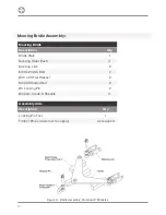
Mooring Bridle Assembly:-
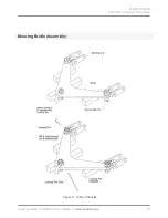
6. Use a suitable lifting device such as a pallet lifting trolley to move the bridle assembly
into position under the central float.
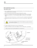
7. Insert mooring wear bushes into the float mooring points, 4 places.
8. Align the mooring links with the float mooring points and insert M36 mooring bolts
pointing tail out (DO NOT FIT ANY WASHERS UNDER THE HEAD OF THE MOORING
BOLT).
Lightly coat each bolt tail and nut with an anti-seize compound or molybdenum disulphide grease.
5. Fit a Ø36 flat washer and M36 slotted nut to each of the mooring bolts. Tighten until
firm.
6. Fit a Ø6 locking pin through the hole in each M36 bolt tail.
7. Using the locking pin tool, bend the straight end of the locking pin to a right angle.
Do not over tighten the M36 mooring bolts. Once assembled the mooring links should rotate
freely about float mooring points.
Apply marine grease over any exposed threads for ease of maintenance.
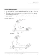
Figure 12 – Buoy Mooring Attachments
BRIDLE INSTALLATION
Summary of Contents for ATLANTIC-3000
Page 2: ...2 Version No Description Date Author Approved 1 0 Manual Launch October 2018 G Percy G Percy ...
Page 8: ...8 Technical Drawings ...
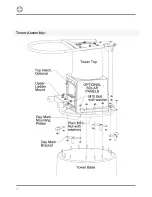
Page 14: ...14 Tower Assembly ...
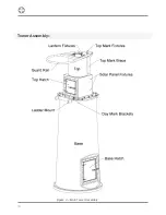
Page 16: ...16 Tower Assembly Figure 4 Main Tower Assembly ...
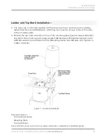
Page 20: ...20 Ladder and Top Mark Installation Figure 6 Ladder Installation ...
Page 32: ...32 Electronic Equipment Installation ...
Page 34: ...34 Notes ...

