)8(/6<67(0
6HDOLQH2ZQHUV0DQXDO3DJH
FUEL SYSTEM
The fuel system undergoes stringent quality checks
during production and then again before the boat
leaves the factory. All fittings are of the compression
type and meet stringent European standards. Where
two fuel tanks are used provision has been made to
use any one tank to run both engines etc (For fuel tap
positions and diagrams please refer to the back of this
manual - FUEL SYSTEM).
Fuel Filters - The fuel filters are mounted on the front
of the lazarette. They have drain taps mounted at their
bases for draining any water that may have
accumulated in the system. This should be checked
regularly, particularly when you fill your tanks with fuel
of doubtful quality.
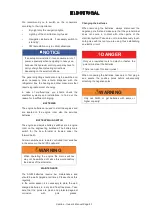
WARNING
Replace the water separator filters annually.
Periodically check the pipe work and fittings for
corrosion or wear. Check that the flexible hoses in
the engine compartment are not damaged or
perished. Replace if necessary Clean the fuel
deck vent gauze if required.
Venting the Fuel System - It will be necessary to vent
(bleed) the fuel system should any work be carried out
or the fuel tank has been run empty.
Connect a transparent hose to the bleed nipple (1).
Feed the hose to a container to avoid spillage. Open
the bleeding nipple and pump fuel with the hand pump
(2) until the fuel is free from bubbles. Close and
tighten the bleed nipple.
Pump a further 10 times on the hand pump.
Resistance in the hand pump can feel heavy, but this
is completely normal and necessary to bleed the
system.
Fuel Valves
- Fuel valves are located in the forward
face of the cockpit starboard seating module. They
control fuel flow to their respective engine(s). Fuel
valves should be turned off when leaving the boat to
prevent fuel siphoning from the tank.
Fuel Fillers
- The fuel fillers are located on the craft
centre line, under the bathing platform to cockpit
step. The fuel vents are located just above the fuel
fillers. When the tanks are nearly full, fuel may spill
from them. Inside the mouth of the fuel vent there is
a fine wire mesh, this must not become blocked or
you will experience problems filling your tanks and
possible difficulty with your engines.
Fuel Tanks
– The fuel tanks with a capacity of
approx. 600 l are located in the engine room. They
are equipped with electrical transmitting devices,
inspection hatch and ventilation.
CAUTION
Prevention of damage to fuel lines.
Avoid damaging fuel lines, wherever possible fuel
lines are protected by rigid conduit, do not tamper.
Ensure the snap on covers are replaced after
inspection or work.
WARNING
In the event of fuel odour being present, switch off
engine(s) and trace the source immediately.
Check fuel tank lines and joints visually. DO NOT
smoke or use naked lights. Switch off all electrics
at source. The bilges should be well ventilated
and spillage dried out as soon as possible. DO
NOT use the engines until all vapour has been
removed. Fuel vapour is highly explosive
Summary of Contents for S450
Page 1: ... ...
Page 2: ... ...
Page 6: ... 6HDOLQH 2ZQHU V 0DQXDO 3DJH ...
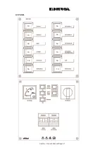
Page 55: ... 75 6HDOLQH 2ZQHU V 0DQXDO 3DJH AC PANEL 10 10 16 10 16 16 16 16 16 10 16 10 ...
Page 81: ... 7 1 6HDOLQH 2ZQHU V 0DQXDO 3DJH ...
Page 82: ... 6HDOLQH 2ZQHU V 0DQXDO 3DJH DATA SHEETS DIAGRAMS PRINCIPAL DIMENSIONS ...
Page 84: ... 6HDOLQH 2ZQHU V 0DQXDO 3DJH DECK PLAN ...
Page 86: ... 6HDOLQH 2ZQHU V 0DQXDO 3DJH SYSTEM CONTROL POINTS ...
Page 88: ... 6HDOLQH 2ZQHU V 0DQXDO 3DJH EQUIPMENT LOCATION ACCOMMODATION SPACE ...
Page 90: ... 6HDOLQH 2ZQHU V 0DQXDO 3DJH GAS SYSTEM LAYOUT ...
Page 92: ... 6HDOLQH 2ZQHU V 0DQXDO 3DJH FIRE PROTECTION SYSTEM 3 4 1 5 6 8 1 2 7 8 8 1 ...
Page 94: ... 6HDOLQH 2ZQHU V 0DQXDO 3DJH BLACK WATER SYSTEM ...


