4.1.2.
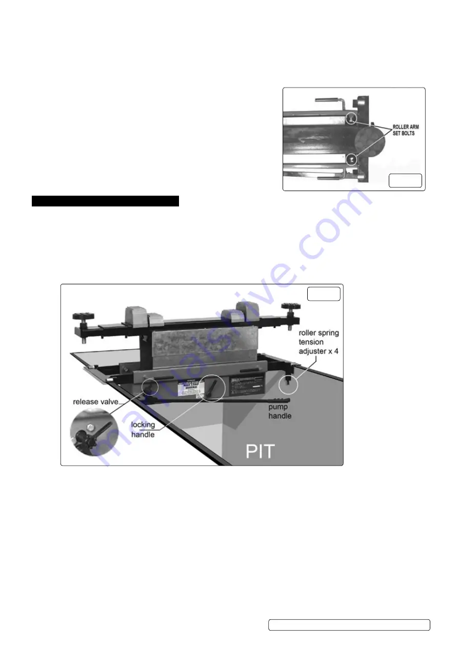
With the beam central on the ramp/pit and the rollers located on the runners, tighten the roller arms set bolts. (fig.3)
4.1.3.
Adjust the spring tension on all four rollers (fig.4) so that the rollers will just support the weight of the jacking beam on its own
and allow it to travel freely over the ramp/pit. note that too much spring tension will cause the rollers to jam against the side arms.
When the jacking beam is in use the weight of the vehicle will overcome the spring tension, pushing the rollers upwards and
allowing the jacking beam to settle onto the two roller arms.
4.1.4.
Before use you must remove the transportation plug and fit the supplied vent valve in its place. (fig.2)
4.2.
using hook arm supports.
4.2.1.
Alternative hook arm supports are supplied for use where the runners on
a ramp
or pit are vertical (fig.5). Loosen the roller arm set bolts (fig.3) and
withdraw the roller arms from the main frame. Insert the hook arm supports
ensuring that the channel faces downwards and set them to match the
width of the vertical runners. The hook arm supports should be extended
equally either side of the jacking beam. Tighten all four support arm set bolts
before mounting the jacking beam onto the runners.
5. OpeRaTiOn
5.1.
Jacking beam controls (fig.4).
5.1.1.
Familiarise yourself with the controls of the jacking beam before operating.
note: The further anticlockwise you turn the release valve the faster the beam will lower. Familiarise yourself with this before
operating under load.
5.1.2.
As a safety feature the beam has two locking positions which are controlled by the locking lever.
5.1.3.
When jacking, the locking lever will engage at certain heights (approx 100mm and 240mm of lift height) to prevent the jack from
lowering all the way should the release valve be accidentally moved, to lower the jack past this point you must raise the jack a small
amount and then turn the locking lever clockwise whilst turning the release valve anticlockwise.
5.2.
To jack a vehicle.
5.2.1.
With the beam in the lowered position, locate it under the vehicle at the position that you require to lift.
note: ensure you use the vehicle manufacturer’s designated jacking points.
5.2.2.
The majority of lift applications require the use of two saddles.
5.2.3.
evaluate which saddle pair combinations are best suited to the job.
5.2.4.
The saddles at either end are adjustable, and may be raised or lowered by screwing clockwise or anticlockwise in order to give the
beam clearance from the underside of the vehicle.
5.2.5.
Adjust the telescopic arms to line up the saddles with the jacking points of the vehicle.
5.2.6.
Turn the release valve clockwise and start to raise the jack by operating the pump handle (Fig.4). Raise the beam in short increments
and ensure the saddles are centred on the jacking points.
5.2.7.
once you have established the setup is stable you may proceed to lift the vehicle to the required height.
5.2.8.
Make sure the locking handle is engaged, if it is not engaged you need to raise or lower the beam to the closest locking point,and
check the locking handle engages.
5.2.9.
To lower the vehicle follow the procedure outlined in 5.1.3 Jacking Beam Controls.
fig.3
fig.4
SJBeX200.V2, SJBeX300 | Issue 6 (2) 14/08/18
Original Language Version
© Jack Sealey limited


