background image

3 Operation

3--18

Edge Reinforcer Issue 1

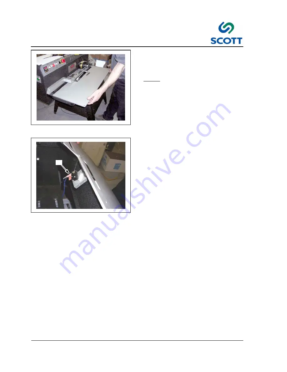
Fig. 3-34. Lift Table Off Locating Pins

Step: 10.

Lift the outside of the table until it is off

the two locating pins and slide the table

slightly away from the machine by pulling

it towards you.

NOTE!

Do Not Pull Table Free of Machine.
The Trip Switch is still connected.

B

Fig. 3-35. Disconnect the Trip Switch

Step: 11.

Disconnect the wires to the trip switch (B)

which is located inside the table.

Step: 12.

Put table in safe place.

(See “Caution” paragraph above).

Step: 13.

Clean machine as necessary.

Step: 14.

Reinstall table in reverse order of

disassembly.

Summary of Contents for Edge Reinforcer

Page 1: ...Copy No Instruction Manual Model No Scott Edge Reinforcer Year of Manufacture 2006 Manufactured by Document Number R99999 2 Issue 1 Date of Issue July 2006...

Page 2: ...ISSUE NOTE This is Issue 1 Date of Issue July 2006 Copyright 2006...

Page 3: ...ean 1 10 1 6 3 Grease and Oil 1 10 1 6 4 Manual Usage 1 10 2 INSTALLATION 2 1 2 1 Installation Requirements 2 3 2 2 Pre Installation Requirements 2 4 2 3 Uncrating Placement 2 5 2 3 1 Main Machine 2 5...

Page 4: ...Spare Parts 4 3 4 1 1 Machine Lubrication 4 4 4 1 2 Installing New Trip Switch 4 6 4 1 3 Replacing Cut Off Knives 4 8 4 1 4 Removing Installing the Upper and Lower Cut Off Knife Assembly 4 9 4 1 5 Pa...

Page 5: ...Table of Contents V Scott Edge Reinforcer 5 22 Pressure Sensitive Tape Assembly 5 46 5 23 Leg Extension Assembly 5 48 5 24 Rail Leg Assembly 5 50 5 25 Leg Extension Assembly 5 52 6 SCHEMATICS 6 1...

Page 6: ...1 Introduction Safety 1 1 Edge Reinforcer Issue 1 1 INTRODUCTION SAFETY Edge Reinforcer Issue 1...

Page 7: ...1 Introduction Safety 1 2 Edge Reinforcer Issue 1...

Page 8: ...dge Reinforcer Issue 1 1 1 Introduction The Scott Edge Reinforcer machine lays reinforcing tape within the outside edges of the sheet at the rate of up to 3 000 sheets per hour Fig 1 1 Edge Reinforcer...

Page 9: ...m 3 1 2 WIDTH x 8 LENGTH MINIMUM Paper 32lb Bond to 17 Point Board Plastic Length 203 2 mm 8 MINIMUM ANY LENGTH MAXIMUM Plastic 14 3 mm 19mm 9 16 3 4 Motor FEED 1 3 HP DRIVE 1 6HP Electrical Requireme...

Page 10: ...re installing and operating or performing maintenance and clean up procedures on the machine it is suggested that the safety program be reviewed to ensure that it covers the possible hazards that migh...

Page 11: ...hbutton must be manually pulled out to reset STOP Fig 1 4 Know How to Stop Machine Set Key Switch to SAFE 1 3 2 Stop and Safe The machine operator clean up and maintenance personnel MUST be shown how...

Page 12: ...ety 1 7 Edge Reinforcer Issue 1 Fig 1 6 Guards Must Be In Place to Run Machine 1 3 4 Guards and Covers All safety guards protective screens and covers MUST be in place and securely fastened before ope...

Page 13: ...ate Personal Danger 1 4 1 Warnings AN OPERATING PROCEDURE PRACTICE ETC WHICH IF NOT CORRECTLY FOLLOWED COULD RESULT IN PERSONAL INJURY OR LOSS OF LIFE WARNING CAUTION Fig 1 8 Cautions Indicate Potenti...

Page 14: ...e 1 1 5 On Machine Warnings Fig 1 10 Burn Hazard Heat Rollers 1 5 1 Hazards Observe Hazard signs There is burn hazard sign on top of the heat roller unit Fig 1 11 Voltage Warning There is a hazardous...

Page 15: ...area Fig 1 13 Keep Work Area Clean and Neat 1 6 2 Keep Area Clean Loose materials tools and equipment not essential to the operation of the machine must be removed from the machine work area Fig 1 14...

Page 16: ...2 Installation 2 1 Edge Reinforcer Issue 1 2 INSTALLATION Edge Reinforcer Issue 1...

Page 17: ...2 Installation 2 2 Edge Reinforcer Issue 1...

Page 18: ...cott Edge Reinforcer Environmental requirements unpacking instructions electrical and physical specifications are included This information should be used as a reference during the development of site...

Page 19: ...s Power location and rating of power connections Floor strength Level floor Adequate space must be provided around all four sides of the machine to permit normal operation and maintenance procedures T...

Page 20: ...lag screws holding machine to shipping skid Step 4 Raise main machine with fork lift remove shipping skid assembly from under machine Step 5 Lower main machine to floor Step 6 Remove all protective wr...

Page 21: ...3 Operation 3 1 Edge Reinforcer Issue 1 3 OPERATION Edge Reinforcer Issue 1...

Page 22: ...3 Operation 3 2 Edge Reinforcer Issue 1...

Page 23: ...ALL MACHINE STOPPING CONTROLS REVIEW MANUAL FOR EMERGENCY STOP BUTTON LOCATION Do not attempt to operate the machine before reading and understanding the manual Pay close attention to all WARNINGS CAU...

Page 24: ...3 Operation 3 4 Edge Reinforcer Issue 1...

Page 25: ...Control Panel Layout Fig 3 1 Control Panel Fig 3 2 Emergency Stop 3 2 2 Machine Stopping Device 3 2 2 1 Emergency Stop Red Pushbutton Stops the machine drive immediately The Emergency Stop button is l...

Page 26: ...ter Set Point or Other Return Key Resets the controller to its normal status Also stops auto tuning output percentage monitoring and manual mode operation Press for 6 seconds Long Scroll Allows more p...

Page 27: ...be drawn into the machine The button will be illuminated when the feed in ON Fig 3 7 Drive Mode Selector Switch 3 2 2 6 Drive Mode Selector Switch The Drive Mode Selector switch controls the drive mot...

Page 28: ...he Clutch Engaged indicator light is useful for timing sheets fed into the machine The Clutch Engaged light should turn off after each sheet fed Fig 3 11 Clutch and Brake Potentiometers 3 2 4 Brake an...

Page 29: ...eat Controller Step 2 Turn the Heater to ON NOTE The optimum temperature is between 190_ 200_F Keep the temperature as low as possible to prevent tape stretch and the removal of water from the paper T...

Page 30: ...inst it The polyester tape is on 3 cores Step 1 Place the reel of tape on the reel holder Step 2 You may use a small piece of self adhesive tape to fasten the end of the polyester tape to the applying...

Page 31: ...trip of tape to be drawn around the strip applying roller Fig 3 18 Turn the Drive Switch to ON Step 6 Turn Drive switch to on Step 7 Remove the piece of self adhesive tape from the roller and use it t...

Page 32: ...low the cross over arm By adjusting this collar back and forth on its spindle the tape can be controlled so that it will be applied in the correct position on the paper Fig 3 21 Insert Spring Loaded P...

Page 33: ...a proper cut The cut off guide finger detects the edge of the sheet for the knife to cut the film The cut off guide finger is mounted in a circular holder which allows it to be adjusted with respect...

Page 34: ...er adjustment is necessary Fig 3 25 Loosen Guide Finger Set Screw Step 4 Loosen set screw securing guide finger in place Fig 3 26 Rotate Guide Finger Assembly Dimension of Cut Step 5 Hold on to knife...

Page 35: ...rapidly If the sheets are fed too rapidly they may overlap each other before they get to the spacer finger which sometimes may cause the sheets to stop at the cut off guide finger and jam the machine...

Page 36: ...in any way even small dents or burrs on the top surface may tend to snag the sheets as they go through and can cause operating difficulties Fig 3 29 Jog Last Sheets Out of Machine and Turn Feeder and...

Page 37: ...OTE There is a flat on the hub which provides the clearance needed to lift off table B Fig 3 32 Rotate the Cut Off Guide Finger Above Table Step 8 Make sure that the cut off guide finger B is NOT down...

Page 38: ...from the machine by pulling it towards you NOTE Do Not Pull Table Free of Machine The Trip Switch is still connected B Fig 3 35 Disconnect the Trip Switch Step 11 Disconnect the wires to the trip swit...

Page 39: ...f the machine which prevents the arm from being rotated beyond a certain point However in normal operation the arm should never come in contact with this pin and should stop approximately 1 2 from the...

Page 40: ...t times The ability of the cut off guide finger to accurately gauge the cutting is affected by the rigidity of the paper Since some papers of the same weight vary in rigidity it is not possible to pre...

Page 41: ...ep 4 Slide the motor forward toward the feed end until the belt is reasonably tight NOTE DO NOT MAKE THE BELT TOO TIGHT IT WILL CAUSE THE DRIVE CLUTCH TO BIND SHOULD THIS OCCUR THE CLUTCH MAY FAIL TO...

Page 42: ...d with particular care When feeding lightweight stocks care should be taken to keep the sheet against the left hand side guide so the sheets get started into the machine straight A SHEET FED CROOKED W...

Page 43: ...is is caused by the last sheet stopping before the switch lever can come up overlapping the next fed sheet FIRST SHEET STOPS TOO LATE The switch needs adjustment When this happens there will be tails...

Page 44: ...forced sheet since it will not change the color of the printing On some coated stocks PST will produce a better job PST is immediately available from stock in 3 4 and 9 16 wide reels Reels are 5 000 6...

Page 45: ...drum bar as shown in Fig 3 47 Fig 3 48 Install Self Adhesive Tape as Shown Step 4 Mount the roll of tape Step 5 Position the tape guide bar holding the collars so that the tape comes off about 4 from...

Page 46: ...hesive side is facing out Step 8 Loop the tape over roller and stick the end of the tape to the Heat Roller B NOTE The Heat must be off Step 9 Run 2 3 sheets of stock and discard them so that the fing...

Page 47: ...r will change the direction of travel of the sheet The large roller is mounted on a 3 4 inch diameter shaft which is held by ball bearings in the front and rear gear housing plates If you look at the...

Page 48: ...der Fig 3 53 Feed a Few Sheets Step 3 Turn the machine on and feed a few sheets Watch the inside edge of the sheets near the strip applying roller as they pass through the machine REMOVE POLYESTER FIL...

Page 49: ...holder back and forth until the tape is evenly applied to the top of the sheet Step 7 Thread polyester tape in machine and operate machine 3 4 5 Machine Cleaning Use compressed air to blow dust and p...

Page 50: ...4 Maintenance 4 1 Edge Reinforcer Issue 1 4 MAINTENANCE Edge Reinforcer Issue 1...

Page 51: ...4 Maintenance 4 2 Edge Reinforcer Issue 1...

Page 52: ...wn time Scott Office Systems recommend that you keep them in stock in the quantities shown Part Number Part Description Quantity Per Package HW 74090 O Ring 6 R 0111 A Upper Lower Cutting Knives 2 R 9...

Page 53: ...lant 40 Hours Chains Gears in Box Lubriplate Every 200 Hrs Operators Lubrication Tasks Quick Reference Chart Fig 4 1 Oil Cutting Package Gears Oil in back of the gears located on back side of cutting...

Page 54: ...orcer Issue 1 Fig 4 2 Lubricate Chains and Gears with Light Oil It is also a good idea to apply a small amount of light oil to the chains and gears located inside of the drive box This should be done...

Page 55: ...is mounted on a small metal block with two screws This block is mounted on a larger block by a socket head screw By loosening the socket head screw you can adjust the position where the switch trips...

Page 56: ...1 2 Above Table Top Step 9 Now depress the switch lever until you hear the switch click Step 10 Clip the switch lever off with cutters so that the lever is approximately 1 2 above the table top Step 1...

Page 57: ...o replace the knives put in a new knife shim It is held in position by the upper knife blade A C D Fig 4 8 Make Sure That Upper Blade Does Not Touch Ring or Springs Care should be taken when replacing...

Page 58: ...nd to Scott for service To repair or to return to Cut Off Assemblies to factory for repair Step 1 Remove the Heat Roller Guard A B C Fig 4 10 Rotate the Cut Off Guide Fingers Clear of the Table Step 2...

Page 59: ...ball holder plate D Step 5 Remove the table E Fig 4 13 Remove Lower Cut Off Step 6 Removing the set screw which holds the knurled drive roller E in place E Fig 4 14 Remove the Knurled Drive Roller Ste...

Page 60: ...Fig 4 16 Remove Upper Cut Off Mounting Screws and Clamps Step 9 Remove the two socket head screws and round clamps which hold the upper cut off assembly in the front plate of the gear box housing Fig...

Page 61: ...ghtly into a carton This carton should be placed in a larger carton with plenty of padding all around making sure it is tightly packed so that it will not be damaged during shipping Note ALWAYS RETURN...

Page 62: ...hrough the front wall of the gear box housing Make certain that the assembly is inserted square to the wall It may be necessary to rotate the assembly slightly so that it will slide in easily It will...

Page 63: ...at the point where it would normally start to cut Then slide the lower assembly into place with the knives in contact with each other the lower knife will be behind the upper knife Fig 4 24 Rotate Hou...

Page 64: ...cutting shaft so that the flat is in the 2 00 position Fig 4 27 Reinstall Knurled Drive Roller Step 12 Replace the knurled drive roller and set screw Note It is very important to leave a slight space...

Page 65: ...5 Parts Page 5 1 Scott Edge Reinforcer Issue 1 07 2006 5 PARTS Scott Edge Reinforcer R99999 2 Issue 1 07 2006...

Page 66: ...dress City State Country Zip Code and Machine Serial Number 2 Order by part number and description as shown in the manual 3 Specify how shipments are to be made Freight Parcel Post or Express If routi...

Page 67: ...dit can be approved 2 All shipments returned MUST contain a copy of the Invoice Number or Packing List that parts were received on and the reason for return noted Shipments may be refused if the above...

Page 68: ...Page 5 4 5 Parts Scott Edge Reinforcer Issue 1 07 2006 5 1 Base Assembly...

Page 69: ...MAIN FRAME 2 14 R 0036 POST MAIN FRAME SPACER 1 15 R 0218 PLATE MOTOR MTG 1 16 R 0206 PLATE FRONT INSIDE 1 17 R 0207 PLATE REAR INSIDE 1 18 R 0208 PLATE FRONT OUTSIDE 1 19 R 0209 PLATE REAR OUTSIDE 1...

Page 70: ...Page 5 6 5 Parts Scott Edge Reinforcer Issue 1 07 2006 5 2 Base Assembly...

Page 71: ...Assembly Page 5 7 Scott Edge Reinforcer Issue 1 07 2006 ITEM PART DESCRIPTION REQ ITEM PART DESCRIPTION REQ 1 R 0705 ELECTRICAL CONTROL UNIT 1 HW 51210 SCREW SOC HD 4 HW 49040 WASHER FLAT 4 2 RP 08037...

Page 72: ...EN FROM BASE ASSEMBLY PAGE REF R 0206 FRONT INSIDE PLATE TAKEN FROM BASE ASSEMBLY PAGE REF R 0208 FRONT OUTSIDE PLATE TAKEN FROM BASE ASSEMBLY PAGE REF R 0209 REAR OUTSIDE PLATE TAKEN FROM BASE ASSEMB...

Page 73: ...GUIDE FEED 1 10 R 0703 GUARD HEAT ROLLER 1 HW 54060 SCREW FLAT HD 2 11 R 0031 BAR SIDE GUIDE MTG 1 HW 51230 SCREW SOC HD 4 12 R 0032 PLATE FEED 1 HW 56080 PIN DOWEL 2 13 R 0180 PLATE SWITCH MTG 1 HW 5...

Page 74: ...SIDE PLATE AND R 0207 REAR INSIDE PLATE TAKEN FROM BASE ASSEMBLY PAGE REF R 0021 OUTSIDE GEAR HOUSING PLATE TAKEN FROM BASE ASSEMBLY PAGE REF R 0021 OUTSIDE GEAR HOUSING PLATE Page 5 10 5 Parts Scott...

Page 75: ...110 RING RETAINING 2 4 R 0183 ARM BELT TAKE UP 1 5 PULLEY GEARBELT 1 6 R 0178 SHAFT GEARBELT IDLER 1 HW 59030 KEY SQUARE 1 7 HW 56180 PIN DOWEL 1 8 HW 67060 BEARING NEEDLE 2 9 PULLEY GEARBELT 1 10 HW...

Page 76: ...0206 FRONT INSIDE PLATE AND R 0207 REAR INSIDE PLATE TAKEN FROM BASE ASSEMBLY PAGE REF R 0021 OUTSIDE GEAR HOUSING PLATE TAKEN FROM BASE ASSEMBLY PAGE Page 5 12 5 Parts Scott Edge Reinforcer Issue 1...

Page 77: ...8702 SPROCKET 1 HW 52080 SCREW SET 1 HW 84020 BALL NYLON 1 4 R 0221 SHAFT MAIN DRIVE 1 HW 59055 KEY SQUARE 1 5 R 9003 PULLEY V BELT 1 6 HW 61050 RING RETAINING 1 7 HW 52190 SCREW SET 2 8 HW 98030 COLL...

Page 78: ...REF R 0218 MOTOR MOUNTING PLATE TAKEN FROM BASE ASSEMBLY PAGE Page 5 14 5 Parts Scott Edge Reinforcer Issue 1 07 2006 5 6 Motor Assembly...

Page 79: ...SOC HD 6 HW 49040 WASHER FLAT 6 2 R 0219 RAIL MOTOR MTG 2 3 R 0220 NUT T 4 4 R 9004 PULLEY V BELT DRIVE 1 5 HW 95300 CLUTCH BRAKE CLUTCH 1 6 HW 55427 SCREW HEX HD 2 HW 49170 WASHER LOCK 2 7 HW 55428 S...

Page 80: ...4 4 2 2 REF MOTOR ASSEMBLY REF GEAR BELT IDLER ASSEMBLY REF PLASTIC CUT OFF UNIT UNIT REF HEAT ROLLER UNIT REF MAIN DRIVE SHAFT ASSEMBLY Page 5 16 5 Parts Scott Edge Reinforcer Issue 1 07 2006 5 7 Be...

Page 81: ...bly Page 5 17 Scott Edge Reinforcer Issue 1 07 2006 ITEM PART DESCRIPTION REQ ITEM PART DESCRIPTION REQ 1 HW 75030 BELT V 1 2 HW 76100 BELT GEAR 1 3 HW 77010 CHAIN ROLLER 1 HW 77020 CONNECTING LINK 1...

Page 82: ...Page 5 18 5 Parts Scott Edge Reinforcer Issue 1 07 2006 5 8 Cover Assembly...

Page 83: ...r Assembly Page 5 19 Scott Edge Reinforcer Issue 1 07 2006 ITEM PART DESCRIPTION REQ ITEM PART DESCRIPTION REQ 1 R 0042 COVER UPPER GEAR HOUSING 1 SCREW FLAT HD 4 2 R 9908 PLATE MACHINE NAME 1 HW 5535...

Page 84: ...206 FRONT INSIDE PLATE TAKEN FROM BASE DRIVE UNIT REF HW 99010 COTTON WHITE BELT TAKEN FROM CONVEYOR BELT ASSEMBLY PAGE Page 5 20 5 Parts Scott Edge Reinforcer Issue 1 07 2006 5 9 Front Roller Belt As...

Page 85: ...07 2006 ITEM PART DESCRIPTION REQ ITEM PART DESCRIPTION REQ 1 HW 57170 PIN SPRING 4 2 R 0197 BLOCK SHAFT MTG 2 3 HW 51240 SCREW SOC HD 4 4 R 7803 SHAFT 1 5 HW 61210 RING GRIP 8 6 HW 66010 BEARING BAL...

Page 86: ...REF R 0206 FRONT INSIDE PLATE TAKEN FROM BASE DRIVE UNIT Page 5 22 5 Parts Scott Edge Reinforcer Issue 1 07 2006 5 10 Tension Arm Assembly...

Page 87: ...LAT HD 2 3 R 7804 SHAFT 1 4 HW 90010 PULLEY V BELT 1 5 HW 67050 BEARING NEEDLE 2 6 R 6402 SLEEVE PULLEY MTG 1 7 R 0147 ROLLER FEED TAPE DRIVE 1 8 R 0081 ARM TENSION 1 9 HW 51210 SCREW SOC HD 2 10 HW 6...

Page 88: ...REF R 0046 PAPER LONG GUIDE TAKEN FROM BASE DRIVE UNIT Page 5 24 5 Parts Scott Edge Reinforcer Issue 1 07 2006 5 11 Support Mounting Assembly...

Page 89: ...unting Assembly Page 5 25 Scott Edge Reinforcer Issue 1 07 2006 ITEM PART DESCRIPTION REQ ITEM PART DESCRIPTION REQ 1 HW 54090 SCREW FLAT HD 2 2 R 0083 PLATE SUPPORT 1 3 R 0082 PLATE SUPPORT MTG 1 4 H...

Page 90: ...REF R 0218 MOTOR MOUNTING PLATE TAKEN FROM BASE ASSEMBLY PAGE Page 5 26 5 Parts Scott Edge Reinforcer Issue 1 07 2006 5 12 Electric Motor Assembly...

Page 91: ...embly Page 5 27 Scott Edge Reinforcer Issue 1 07 2006 ITEM PART DESCRIPTION REQ ITEM PART DESCRIPTION REQ 1 HW 55170 SCREW CARRIAGE 4 HW 49050 WASHER FLAT 4 HW 60060 NUT HEX 4 2 HW 90020 PULLEY VARIAB...

Page 92: ...3 SUPPORT PLATE TAKEN FROM SUPPORT MOUNTING ASSEMBLY PAGE REF R 0082 SUPPORT MOUNTING PLATE TAKEN FROM SUPPORT MOUNTING ASSEMBLY PAGE REF R 0206 FRONT INSIDE PLATE TAKEN FROM BASE DRIVE UNIT Page 5 28...

Page 93: ...5 Parts 5 13 Conveyor Belt Assembly Page 5 29 Scott Edge Reinforcer Issue 1 07 2006 ITEM PART DESCRIPTION REQ ITEM PART DESCRIPTION REQ 1 BELT COTTON WHITE 1 2 HW 75020 BELT V 1...

Page 94: ...REF R 0030 PLATE INSIDE GEAR HOUSING REF R 0021 PLATE OUTSIDE GEAR HOUSING Page 5 30 5 Parts Scott Edge Reinforcer Issue 1 07 2006 5 14 Pivot Shaft Assembly...

Page 95: ...DOWEL 2 2 HW 98050 COLLAR 1 3 R 0100 SHAFT BEARING HOUSING 1 4 HW 52080 SCREW SET 2 HW 84020 BALL NYLON 2 5 R 0196 BLOCK BOTTOM ROLLER PIVOT 1 6 HW 56030 PIN DOWEL GROOVED 2 7 HW 80092 SPRING EXTENSI...

Page 96: ...REF R 0030 PLATE INSIDE GEAR HOUSING REF R 0196 BLOCK BOTTOM ROLLER PIVOT FROM PREVIOUS PG Page 5 32 5 Parts Scott Edge Reinforcer Issue 1 07 2006 5 15 Bearing Housing Lower Appling Shaft Assembly...

Page 97: ...NG 4 5 HW 66020 BEARING BALL 2 6 HW 52080 SCREW SET 1 HW 84020 BALL NYLON 1 7 R 0195 HOUSING BEARING 1 8 HW 62030 RING RETAINING 2 9 R 0204 SHAFT LOWER APPLING ROLLER 1 10 HW 69175 WASHER THRUST 11 HW...

Page 98: ...REF R 0030 PLATE INSIDE GEAR HOUSING REF R 0021 PLATE OUTSIDE GEAR HOUSING Page 5 34 5 Parts Scott Edge Reinforcer Issue 1 07 2006 5 16 Slip Ring Brush Assembly...

Page 99: ...1 12 R 0188 SLEEVE SLIP RING MOUNTING 1 HW 52080 SCREW SET 2 HW 84020 BALL NYLON 2 13 C 0829 RING SLIP 2 HOLES 1 14 HW 61050 RING RETAINING 1 15 HW 62050 RING RETAINING 1 16 C 0834 BRUSH SILVER PROBE...

Page 100: ...3 3 VIEW A A B SECTION B B B Page 5 36 5 Parts Scott Edge Reinforcer Issue 1 07 2006 5 17 Upper Lower Knife Holder Assembly...

Page 101: ...INGER 1 10 HW 52004 SCREW SET 2 11 HW 52070 SCREW SET 2 HW 84020 BALL NYLON 2 12 R 0113 FINGER CUT OFF GUIDE 1 13 HW 61150 RING RETAINER BOWED 3 14 R 0172 RING GAGE 1 15 R 0128 ROLLER UPPER PAPER DRIV...

Page 102: ...Page 5 38 5 Parts Scott Edge Reinforcer Issue 1 07 2006 5 18 Housing Assembly...

Page 103: ...006 ITEM PART DESCRIPTION REQ ITEM PART DESCRIPTION REQ 1 HW 66020 BEARING BALL 3 2 R 0109 SPRING RING 1 3 HW 61110 RING RETAINING 2 4 HW 52005 SCREW SET 1 5 HW 64050 BEARING BRONZE 2 6 HW 88050 SPUR...

Page 104: ...Page 5 40 5 Parts Scott Edge Reinforcer Issue 1 07 2006 5 19 Sprocket Mounting Assembly...

Page 105: ...7 2006 ITEM PART DESCRIPTION REQ ITEM PART DESCRIPTION REQ 1 HW 51360 SCREW SOC HD 2 2 HW 82010 CLAMP 2 3 HW 66020 BEARING BALL 2 4 HW 61110 RING RETAINING 1 5 HW 88060 SPUR GEAR 1 6 HW 86010 PULLEY G...

Page 106: ...REF R 0021 FRONT OUTSIDE GEAR HOUSING PLATE TAKEN FROM BASE DRIVE UNIT REF PLASTIC TAPE ROLL Page 5 42 5 Parts Scott Edge Reinforcer Issue 1 07 2006 5 20 Plastic Mounting Hub Assembly...

Page 107: ...BEARING BALL 2 4 RING RETAINING 2 5 C 1509 HUB PLASTIC MTG 1 6 HW 79050 SPRING COMPRESSION 3 7 C 1511 PLUNGER PLASTIC MTG HUB 3 8 C 1505 PLATE PLASTIC MTG HUB 1 9 HW 55360 SCREW DRIVE 3 10 R 0202 HUB...

Page 108: ...OUTSIDE GEAR HOUSING PLATE TAKEN FROM BASE DRIVE UNIT REF R 0030 FRONT INSIDE GEAR HOUSING PLATE TAKEN FROM BASE DRIVE UNIT Page 5 44 5 Parts Scott Edge Reinforcer Issue 1 07 2006 5 21 Roller Mountin...

Page 109: ...PART DESCRIPTION REQ ITEM PART DESCRIPTION REQ 1 R 0051 ROLLER PLASTIC GUIDE 5 HW 56020 PIN DOWEL 5 HW 61188 RING GRIP 10 2 R 0122 BLOCK ROLLER MTG 1 HW 51230 SCREW SOC HD 2 3 HW 57310 PIN SPRING 1 4...

Page 110: ...REF R 0030 FRONT INSIDE GEAR HOUSING PLATE TAKEN FROM BASE DRIVE UNIT REF PRESSURE SENSITIVE TAPE Page 5 46 5 Parts Scott Edge Reinforcer Issue 1 07 2006 5 22 Pressure Sensitive Tape Assembly...

Page 111: ...Edge Reinforcer Issue 1 07 2006 ITEM PART DESCRIPTION REQ ITEM PART DESCRIPTION REQ 1 HW 51360 SCREW SOC HD 2 2 R 0143 BAR MTG 1 3 R 0133 SHAFT STRIP GUIDE 1 4 HW 98030 COLLAR 2 5 HW 51390 SCREW SOC H...

Page 112: ...Page 5 48 5 Parts Scott Edge Reinforcer Issue 1 07 2006 5 23 Leg Extension Assembly...

Page 113: ...EM PART DESCRIPTION REQ ITEM PART DESCRIPTION REQ 1 R 1008 LEG STAND 2 2 R 1001 LEG STAND 2 3 R 1002 LEG STAND EXTENSION 4 4 HW 53150 SCREW BUTTON HD 8 HW 49040 WASHER 8 HW 49230 WASHER INT LOCK 8 HW...

Page 114: ...PREVIOUS PAGE REF R 1008 LEG STAND TAKEN FROM PREVIOUS PAGE REF R 1001 LEG STAND TAKEN FROM PREVIOUS PAGE REF R 1001 LEG STAND TAKEN FROM PREVIOUS PAGE Page 5 50 5 Parts Scott Edge Reinforcer Issue 1...

Page 115: ...EM PART DESCRIPTION REQ ITEM PART DESCRIPTION REQ 1 R 1003 RAIL LONG UPPER SIDE 2 2 R 1006 RAIL LONG LOWER SIDE 2 3 R 1004 RAIL SHORT UPPER MTG 2 4 R 1005 RAIL SHORT LOWER SIDE 2 5 HW 53150 SCREW BUTT...

Page 116: ...REF R 1008 LEG STAND TAKEN FROM PREVIOUS PAGE REF R 1001 LEG STAND TAKEN FROM PREVIOUS PAGE Page 5 52 5 Parts Scott Edge Reinforcer Issue 1 07 2006 5 25 Leg Extension Assembly...

Page 117: ...Extension Assembly Page 5 53 Scott Edge Reinforcer Issue 1 07 2006 ITEM PART DESCRIPTION REQ ITEM PART DESCRIPTION REQ 1 R 1016 GUARD SIDE 2 2 R 1017 GUARD END 2 3 HW 53150 SCREW BUTTON HD 16 HW 4904...

Reviews: