background image

2.4 LED and Acoustic Signal

To visually and acoustically indicate the current operation mode or a malfunction, the
eHealth100 terminal has three LEDs and a buzzer. The terminal should be placed where the
LEDs are easily visible. 
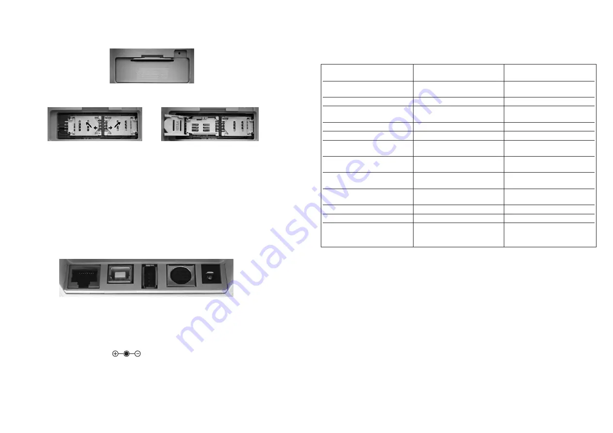
The following states can be shown combining the LED and the buzzer: 

* device firmware upgrade

TTable 2: LED Display and acoustic signals

3 T

YPES OF

C

ONNECTION

There are two different default modes for the eHealth100. Depending on the firmware version,
upon delivery the terminal will boot either as MKT+ (multi-functional terminal) or as SICCT. 

If the MKT+ firmware is deployed on the eHealth100 terminal, the device will boot as an
MKT+ terminal in USB mode by default. If the SICCT firmware is deployed on the terminal,
the device will boot as a SICCT terminal in Ethernet mode by default.

To check the firmware deployed on your device, please go to Menu 

General 

Version. 

MKT+ firmware versions are generally indicated by the letter "u" (e.g. 0.25u), SICCT firmware
versions are indicated by the letter "e" (e.g. 0.26e). You will find the current MKT+ and SICCT
firmware versions at www.scmmicro.com/eHealth100.

If required, you can switch between MKT+ (USB) and SICCT (Ethernet) mode. To do so,
please go to Menu 

Communication

Protocol Settings and choose the respective protocol. 

7

There are also two slots for Secure Module Cards (SMC) in ID-000 format to enable secure
data communication. These are located under the cover on the underside of the terminal. 

Picture 3: Cover at the under side

Pictures 4 and 5: Opening the slots

Before opening the covers to access the SMC slots, it is necessary to remove all connectors
from the plug-in positions.

Note:

New terminals are delivered without seals over the slot covers. However, users may choose
to place a seal over the covers and sign or stamp the seal so it is apparent if the terminal has
been opened or if Factory Reset has been performed. 

2.3 Connections

The following five connections are arranged on the backside of the device: 

1               2            3              4             5

Picture 6: Connections eHealth100

1 - Network / LAN
2 - USB-Client (connection to PC)
3 - USB-Host (for additional devices)
4 - Serial Adapter
5 - Power supply (               5V DC, max. 2,5A)

6

Status

Terminal start, DFU* 

completed
Terminal active
Card inserted, terminal not

powered
Smart card active
Smart card communication
During secure PIN entry

After successful PIN entry

After failed PIN entry

Secure smart card 

communication
Press Abort during PIN entry
Press Delete during PIN entry
Smart card communication

failure

LEDs (green, red, orange)

for eGK and HPC slot

Off

Off
Off

Green on
Green blinking
Orange blinking

Orange on

Green on

Orange blinkin

Green on
Orange blinking
Red on (depending on the

successful or failed PIN 

entry afterwards)

Buzzer

Acoustic signal during booting

after DFU
No sound
No sound

No sound
No sound
One beep for each time a

key is pressed
Two short beeps after 

successful PIN entry
One short beep after failed

PIN entry
No sound

Short beep
Longer beep
No sound

Summary of Contents for eHealth100

Page 1: ...glish Version 1 26 SCM Microsystems GmbH Oskar Messter Straße 13 85737 Ismaning Phone 49 89 9595 5000 Fax 49 89 9595 5555 Manual eHealth100 health card terminal Version 1 26 Date 2007 12 19 Subject to change without notice ...

Page 2: ...7 5 3 9 2 Switching to Ethernet 17 5 3 9 3 Switching to USB 17 5 3 9 4 IP Address and Netmask 18 5 3 9 5 Dynamic Configuration of the IP address 18 5 3 9 6 Manual Configuration of the IP address 18 5 3 10 Factory Reset 18 5 3 11 PIN Management 18 5 3 11 1 Modification of the Administrator PIN APIN 18 5 3 11 2 Modification of the User PIN UPIN 18 5 3 12 Language 19 5 3 13 Diagnosis 19 6 FACTORY RES...

Page 3: ...l where it is in danger of being struck knocked or otherwise harmed Keep dust objects and liquids from entering the terminal danger of short circuit electronic shock The terminal is not waterproof Do not submerge the terminal Safeguard the terminal against rain or other sources of moisture Do not use water or other liquids to clean the terminal When transferring the terminal to another party pleas...

Page 4: ... communication These are located under the cover on the underside of the terminal Picture 3 Cover at the under side Pictures 4 and 5 Opening the slots Before opening the covers to access the SMC slots it is necessary to remove all connectors from the plug in positions Note New terminals are delivered without seals over the slot covers However users may choose to place a seal over the covers and si...

Page 5: ...ed The service query takes place as per the Standard via the UDP Port 4743 Service Query Port The client sends the query either as broadcast or multicast The terminal waits for service queries coming in at a network socket which is configured for receiving either broadcasts or multicasts Note If you have any questions regarding the Ethernet protocol or this chapter please contact your IT administr...

Page 6: ...ATION Make sure the casing and the seals on the underside of the terminal are intact before using the terminal for the first time Please contact your dealer or SCM Microsystems directly if you suspect manipulation First connect the appropriate connection cable serial or USB Afterwards connect the device s power supply with a 230 Volt 50Hz power socket Insert the cable plug into the appropriate soc...

Page 7: ...us icon health professional card a No card inserted no icon b Unsecure mode c Secure mode 3 Status icon electronic health card a No card inserted no icon b Unsecure mode c Secure mode 13 5 MENU To make changes to the terminal menu you must be logged on as administrator or user Users have only limited modification rights 5 1 Structure The following is the default menu structure General Log in Login...

Page 8: ...sociated with F3 7 F4 a Back b No icon if no operation is associated with F4 5 3 Functions 5 3 1 PIN Your PIN Personal Identification Number allows you to access the data stored on the smart card It is important that only you know your PIN Please make sure that a secure and unobserved PIN entry is possible For secure PIN entry only the keys 0 9 of the numeric keypad are used Please confirm the ent...

Page 9: ...ode of operation go to Menu Communication Protocol Settings Ethernet After changing the settings the terminal will restart automati cally and activate the new mode 5 3 9 3 Switching to USB Mode To switch from Ethernet Mode to USB Mode of operation go to Menu Communication Protocol Settings USB After changing the settings the terminal will restart automatically and activate the new mode 17 Test Buz...

Page 10: ... Note It is not possible to launch the web interface while the user menu of the terminal is still active 19 5 3 9 4 IP Address and Netmask To show the IP address and the netmask of the terminal please go to Menu Communication Network Settings IP Address Netmask This information will only be displayed with a working Ethernet connection See also Chapter 3 1 1 Locating the terminal in the Local Area ...

Page 11: ...ware Method In addition to the software method described above Factory Reset can also be achieved by using the Factory Reset switch located on the underside of the eHealth100 terminal 21 The browser will prompt for a username and a password The default user name is admin the default password is admin Click OK to continue Once the login is successful the following screen will appear Click on the Fa...

Page 12: ...ome effective If the menu or the screen saver appears on the display the reset was successful 6 3 More Information After successful Factory Reset the administrator password is reset to admin and the user password is reset to user 7 FIRMWARE UPDATE To update the terminal firmware it is essential to differentiate between SICCT and MKT The firmware update of the SICCT terminal is effected via the LAN...

Page 13: ...served with the firmware update 7 2 Firmware Update in MKT mode via USB cable Firmware can also be updated on the eHealth100 terminal in MKT mode by using a USB cable For the correct deployment of the firmware update please follow these instructions Download the firmware update from the SCM Microsystems website Connect the terminal to the USB cable and the power supply Initiate the firmware update...

Page 14: ...ollowing window opens press Continue Anyway 27 Click browse and select eHealth100 Firmware Click Next A new window appears Click Finish If you deploy the firmware update of the eHealth100 in MKT mode for the first time on your PC and you have not used the MKT installer the Assistant for Searching New Hardware opens Check No not this time and click Continue 26 ...

Page 15: ...to be disposed of in residual waste Please dispose of all WEEE marked products at local waste facilities that are set up to handle the return and collection of electric and electronic equipment The disposal of electric and electronic equipment respective parts of it in residual waste can harm human health and the environment By disposing of WEEE marked products appropriately you are helping to rec...

Page 16: ...30 ...

Reviews: