


I.3
Date Code 20080213
Instruction Manual
SEL-351A Relay
Using the SEL-251 and SEL-267 Relay Settings in the SEL-351A Relay
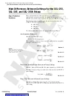
Main Differences Between Settings for the SEL-251, SEL-267, and SEL-351A Relays
Residual-Ground Overcurrent and Time-Overcurrent Pickup Settings
SEL-251-3: Enter directly into SEL-351A “G” elements (eg., 51GP, 50G1P).
SEL-267-5: Convert setting to secondary units, then enter into the SEL-351A
“G” elements.
Equation I.6
Residual-Ground Time-Overcurrent Element Curve Settings
SEL-251-3 and SEL-267-5 Relays: Append a “U” in front of the 51NC setting
value, and enter in the SEL-351A 51GC setting. (See
Element Curve Settings on page I.2
, for example.)
Negative-Sequence Overcurrent Pickup Settings
SEL-251-3: Enter directly into SEL-351A “Q” elements (e.g., 51QP).
SEL-267-5: No negative-sequence elements.
Negative-Sequence Time-Overcurrent Element Curve Settings
SEL-251-3: Append a “U” in front of the 51QC setting value, and enter in the
SEL-351A 51QC setting. (See
Phase Time-Overcurrent Element Curve
, for example.)
SEL-267-5: No negative-sequence time-overcurrent elements.
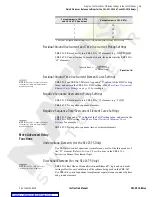
More Advanced Relay
Functions
Undervoltage Elements (for the SEL-251-3 Only)
Use SEL
OGIC®
control equations to simulate any or all of the three modes of
the “27” element. Refer to
Section 2: Specifications
in the SEL
-251-3
Instruction Manual
for element logic.
Directional Elements (for the SEL-267-5 Only)
NOTE:
The SEL-351A-1 does not
include directional elements.
SEL-351A Best Choice Ground Directional Element™ logic and automatic
settings allow for easy emulation of the scheme being used in the SEL-267.
Use SEL
OGIC
control equations to implement separate torque control of phase
and ground elements.
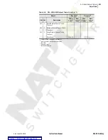
Curve Number in SEL-251-3
and SEL-267-5 Equivalent
Curve Number in SEL-351A
1
U1
a
a
Curve U1 is slightly different from curve 1; time-dial adjustments may be necessary.
2
U2
3
U3
4
U4
A secondary
A primary
CTR setting
(
)
----------------------------------
=
NOTE:
Curve U1 is slightly different
from curve 1, time-dial adjustments
may be necessary.
NOTE:
Curve U1 is slightly different
from curve 1, time-dial adjustments
may be necessary.
Summary of Contents for SEL-351A
Page 10: ...This page intentionally left blank Courtesy of NationalSwitchgear com ...
Page 16: ...This page intentionally left blank Courtesy of NationalSwitchgear com ...
Page 34: ...This page intentionally left blank Courtesy of NationalSwitchgear com ...
Page 126: ...This page intentionally left blank Courtesy of NationalSwitchgear com ...
Page 184: ...This page intentionally left blank Courtesy of NationalSwitchgear com ...
Page 198: ...This page intentionally left blank Courtesy of NationalSwitchgear com ...
Page 228: ...This page intentionally left blank Courtesy of NationalSwitchgear com ...
Page 278: ...This page intentionally left blank Courtesy of NationalSwitchgear com ...
Page 384: ...This page intentionally left blank Courtesy of NationalSwitchgear com ...
Page 410: ...This page intentionally left blank Courtesy of NationalSwitchgear com ...
Page 450: ...This page intentionally left blank Courtesy of NationalSwitchgear com ...
Page 454: ...This page intentionally left blank Courtesy of NationalSwitchgear com ...
Page 472: ...This page intentionally left blank Courtesy of NationalSwitchgear com ...
Page 504: ...This page intentionally left blank Courtesy of NationalSwitchgear com ...
Page 558: ...This page intentionally left blank Courtesy of NationalSwitchgear com ...
Page 562: ...This page intentionally left blank Courtesy of NationalSwitchgear com ...
Page 586: ...This page intentionally left blank Courtesy of NationalSwitchgear com ...
Page 608: ...This page intentionally left blank Courtesy of NationalSwitchgear com ...
Page 666: ...This page intentionally left blank Courtesy of NationalSwitchgear com ...