Assembly
02.00|WDB 99 |en
25
When disconnecting hose lines, the relevant openings must be se-
cured with seal plugs to prevent ingress of dirt or cooling lubricant.
If several units are activated via shared hose lines, feed lines with
the following minimum cross-sections must be used.
Number of stacking pillars with quick-change pallet module
VERO-S NSE plus or direct clamping module WDA 99-70-36
Minimum nominal hose
width
1, 2
4 mm
3, 4, 5, 6
6 mm
Fastening and connection
If you wish to install the unit yourself, please request our draw-
ing.
WDB 99-60
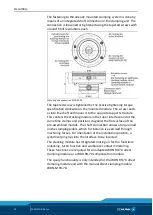
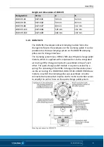
The WDB 99-60 base module is secured on the machine table by
two or four M12 screws and nuts for T-slots suitable for the ma-
chine table. It can be mounted on thread bore hole grid plates
with tapped holes M16 with fit seatings Ø24 H6/H7 and grid spac-
ings of 50 mm. To do so, the basis module is screwed on at a diag-
onal distance of 141.42 mm oriented around the raster plate.
Four M12 screws and 2 M16 screws with 2 washers are included in
the scope of delivery. The nuts for T-slots are not included in the
scope of delivery of the clamping system.
For machine tables with T-slots, various center hole distances are
available. Alternatively, the clamping system can be secured using
two or four BRR 50 clamping pin blanks (see chapter "Accessories"
). There are slots on the bottom of the clamping
system to mount loose T-nuts in order to align the clamping sta-
tions to the machine table slots.
The clamping system can be positioned on machine tables with
hole pattern bore holes or machine tables with T-slots for screw
connection via the central bore hole at the base.
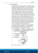
Assembly on grid plates
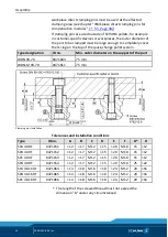
With sleeve, type: HUE 24/25 (Accessory ID no.: 0471632) for
alignment on machine tables with hole pattern bore holes. (Illus-
tration "Mounting the WDB 99-60 on grid plates")
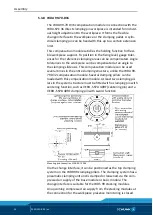
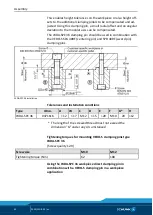
Assembly on T-groove table
With alignment element, type: ARE 25 (accessory ID no.: 1319098)
for alignment on machine tables with T-grooves (Illustration
"Mounting the WDB 99-60 on T-groove table").
5.3
5.3.1


