Maintenance and care
01.00|KSP3-IM, KSP3-LH-IM |en
45
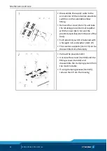
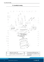
• Remove screws (item 64) and take off
the cover strip (item 8)
• Remove screws (item 66) and take off
the guide strip (item 6)
Remove screws (item 65) and pull out
cover (item 5) together with O-ring (item
45) and O-rings (item 42) out of the
housing. To do this, screw two screws
into the threaded holes as an extraction
tool
for size 64: M3 x L > 25
for size 100: M3 x L > 25
for size 140: M4 x L > 25
for size 160: M3 x L > 25
for size 250: M5 x L > 25
Variant with clamping force
maintenance (AS)
Fasten mounting cover (200) with cheese-
head screws DIN EN ISO 4762. Mounting
for size 64: M3 x 12
for size 100: M5 x 8 – 14
for size 140: M5 x 12 – 16
for size 160: M5 x 16 – 20
for size 250: M6 x 20 – 25


