Maintenance
02.00|1416054_ROTA-M2 + 2 |en-US
47
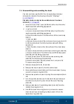
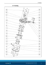
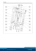
Disassembling and assembling the chuck
The item numbers specified for the corresponding individual
components relate to the drawing in chapter "Drawings"
The lathe chuck can only be disassembled once it has been
removed.
1 Loosen screws of the T-nuts and lift the lathe chuck from the
machine spindle with lifting equipment.
2
→ up to size 630:
a. Loosen screws (item 30) and lift the lathe chuck from the
machine spindle with lifting equipment
b. Place the lathe chuck on the flat surface of the chuck body
(item 1)
→ from size 800:
a. Remove the cover (item 78) and loosen the screws (item 77)
b. Lift the lathe chuck from the machine table with lifting
equipment
c. Place the lathe chuck on the flat surface of the chuck body
(item 1)
d. Loosen screws (item 81) and remove centering pin (item 64)
e. Loosen screws (item 73 and item 74) and lift the base plate
(item 60) with the lifting equipment
f. Loosen screws (item 75) and remove the centering disk
(item 63) from the base plate (item 60)
g. Loosen screw (item 79) and remove the T-nut (item 79)
h. Loosen screw (item 30)
3 Remove screws (items 31, 32 and 42).
4 Remove the mount (item 7) from the lathe chuck
5 Drive cylindrical pin (item 38) out of the mount (item 7) using
a punch, remove O-ring (item 36)
6 Remove the spindle nut (item 9) using the assembly tool (item
49)
7 Turn the spindle (item 8) out of slide (item 16) and remove it
from the mount (item 7), also remove the seat of bearing
(item 29)
8 Remove slide (item 17) and sliding block (item 20) from the
middle drive ring (item 12)
9 Pull off the lower drive ring (item 13), remove the sleeves
(item 14) and two connecting members (item 7) from the
lower drive ring (item 13)
7.3


