background image


Acuity AP820 Laser Scanners 
Rev. 3.3 

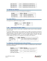
25 


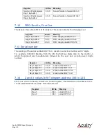
Register


Bit No.


Meaning


Number of Vertical pixels 
Reg.1; Byte 2043


6 to 0


Sensor Number of pixels Bit 6 to 0


Number of Vertical pixels 
Reg.2; Byte 2044


6 to 0


Sensor Number of pixels Bit 13 to 7


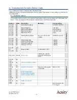
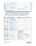
7.12 

FIFO-First In, First Out


The Scanner has a Data FIFO of 512 kByte. This value indicates the charging level. 


Register


Bit No.


Meaning


Reg.1; Byte 2045


7 to 0


FIFO- charging level Bit 7 to 0


Reg.2; Byte 2046


7 to 0


FIFO- charging level Bit 15 to 8


Reg.3; Byte 2047


2 to 0


FIFO- charging level Bit 18 to 16


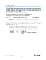
7.13 

Serial number


The reading of the serial number Bit 27 to 0, results in a decimal number with 7 digits. 

For  example,  1009003  Starting from the left,  the first two digits refer  to the  month  on 
which  the  product  was  manufactured,  followed  by  the  year  and  a  continuous  3  digits 
number. 


Register


Bit No.


Meaning


Reg.1; Byte 102


6 to 0


serial number Bit 6 to 0


Reg.2; Byte 103


6 to 0


serial number Bit 13 to 7


Reg.3; Byte 104


6 to 0


serial number Bit 20 to 14


Reg.4; Byte 105


6 to 0


serial number Bit 27 to 21


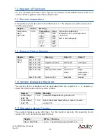
7.14


Z and X values Info-Telegram address 106 to 125


Every one of the 4 values consists of a double register. 

The information in the address 106 to 

113 are indicated as follows: (value * Data resolution) mm 


Register


Bit No.


Meaning


Reg.1


6 to 0


value Bit 6 to 0


Reg.2


6 to 0


value Bit 13 to 7


Summary of Contents for Acuity AccuProfile 820 Series

Page 1: ...ev 3 3 AccuProfile 820 Laser Scanners User s Manual Manual p n LLL008201 Rev 3 4 For use with Acuity products March 15 2017 Acuity A product line of Schmitt Industries Inc 2765 NW Nicolai St Portland...

Page 2: ...of this Agreement You agree upon such termination to return the hardware and software together with all copies of associated documentation In the event of termination the obligation of confidentialit...

Page 3: ...wo conditions 1 This device may not cause harmful interference and 2 this device must accept any interference received including interference that may cause undesired operation Note This equipment has...

Page 4: ...ption 8 3 1 Principles of Operation 8 3 2 Mechanical Dimensions 8 3 3 Contents 12 3 4 Laser Safety 12 3 5 Sensor Maintenance 13 3 6 Sensor Service 13 3 7 Sensor Specifications 13 4 Installation and Ch...

Page 5: ...elegram address 106 to 125 24 7 15 Sensor Data 24 7 16 Version Firmware 24 8 Scanner control 26 8 1 Data format for Register addresses and Data 26 8 2 Register of functions 26 9 Description of the con...

Page 6: ...EthernetScanner_GetScanRawData 39 12 8 Writing Commands to the AP820 39 12 8 1 Examples Laser on Triggering 40 12 8 2 Example Limiting the Range Z 41 12 9 Description of RegisterAddresses accessible...

Page 7: ...eflected light from the surface is viewed from an angle by a two dimensional CCD detector array inside the AP820 sensor The 2D contour profile is calculated by the scanner s microprocessor from the pi...

Page 8: ...le measuring device Target The object of measurement The relative distances from the scanner to the target surface is measured by the sensor Laser Laser line This light visible laser line is emitted f...

Page 9: ...Acuity AP820 Laser Scanners Rev 3 3 7 Attach the Power Data cable s M12 A coded 8 pin female plug to the male...

Page 10: ...ddress of 192 168 1 245 Port 1096 Subnet Mask is 255 255 255 0 For sensors older than 4 2014 please use the IP address of 192 168 123 222 with Port 3000 It can be programmed to use another working IP...

Page 11: ...anner is a laser based device intended for non contact dimension measuring and checking of surface object profiles shapes target positions displacement dimensions sorting and sensing By measuring dist...

Page 12: ...Acuity AP820 Laser Scanners Rev 3 3 9 Figure 1 AP820 5 mechanical dimensions Figure 2 AP820 20 mechanical dimensions Figure 3 AP820 40 mechanical dimensions...

Page 13: ...Acuity AP820 Laser Scanners Rev 3 3 10 Figure 4 AP820 60 mechanical dimensions Figure 5 AP820 80 mechanical dimensions Figure 6 AP820 120 mechanical dimensions...

Page 14: ...Acuity AP820 Laser Scanners Rev 3 3 11 Figure 7 AP820 240 mechanical dimensions...

Page 15: ...line produced by a semiconductor laser diode The laser class of the scanner depends on the model specifications but may range from a Class 2 to a Class 3B laser device in accordance with EN60825 1 200...

Page 16: ...vent such as isopropyl alcohol or water Avoid using pressurized water and do not use abrasive wipes on the optical glass For heavy dust or dirt buildup on the lenses rinse the lenses before wiping cle...

Page 17: ...perpendicular to the target surface that it will be measuring Mount the sensor at the appropriate height above the target surface Consult the product data sheet to determine the sensor s standoff dist...

Page 18: ...uitry and may cause permanent damage 4 2 1 2 Drain Wire Clear The cable may have an un insulated wire drain that connects the stainless steel harness plug of the cable It should also be connected to g...

Page 19: ...ations Check To begin communication with the scanner you may use your own application software or the free demo software described in section 2 1 3 4 3 2 Verifying Operation With the scanner mounted a...

Page 20: ...eflectivity variation surface is it useful to activate the AGC function as described in the register of functions The values in this description that are represented in hexadecimal format will be repr...

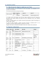
Page 21: ...18 to 21 4 Default IP address 192 168 1 245 22 to 23 2 Default TCP Port 3000 24 to 25 2 26 to 31 6 Working MAC address xx xx xx from serial number 00 08 DC xx xx xx 32 to 35 4 36 to 39 4 Working Gate...

Page 22: ...s Description Meaning Factory setting 00 to 65 66 Status information 1 See Description Scanner data 66 1 Sensor temperature 67 1 Scanner Status Register 68 1 Version evaluation Reg1 69 1 70 to 74 5 Op...

Page 23: ...om the X and Z value as follow X X value 13 0 X max X Scan Range EMB Data resolution mm X max 4096 Z Z value 13 0 Z max Z Measurement Range EMB Data resolution mm Z max 4096 The values X max Z max X S...

Page 24: ...emental Signal A B 90 Phase shifted Input level Low 0 2 V High 5 30 V Register Bit No Meaning Position generator Reg 1 Byte 1525 6 to 0 Position generator Bit 6 to 0 Position generator Reg 2 Byte 1526...

Page 25: ...1 Byte 1563 Bit 0 Byte 1563 Bit 1 Register condition After reset If changed Byte 1563 Bit 2 Byte 1563 Bit 3 Laser on off Byte 1563 Bit 4 Measurement control Continuous mode Single measurement with Tri...

Page 26: ...ontrol was on during automatic operation mode To manually adjust this value aim the scanner to the surface to be scanned Continue by reading the value of the laser output control Now switch the laser...

Page 27: ...ding of the serial number Bit 27 to 0 results in a decimal number with 7 digits For example 1009003 Starting from the left the first two digits refer to the month on which the product was manufactured...

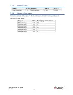
Page 28: ...ion 0 1 mm 1 0 mm 7 16 Version Firmware This is the version of the sensor s Ethernet firmware An ASCII String will be sent For example see below Register Bit No Meaning e g Version 06 0 2 Firmware Reg...

Page 29: ...register In cases of control registers in which the column Bit No is marked with it is sufficient to write the register address to perform the function Registers that are not included in the table in...

Page 30: ...Exposure control Mode 0 Automatic 1 Manual 0 22 1 23 to 27 5 28 1 Reset FIFO Erases all data in the internal FIFO 29 1 Software Trigger Function only when measurement control 1 30 1 Reset Sensor All...

Page 31: ...exposure time 1024 1 sec To identify from which position on the exposure was carried out it is required that a position encoder is plugged to the scanner The position will be saved at the end of an i...

Page 32: ...ther This way it is possible to measure the very same spot on a target with both scanners doubling the effective measuring rate Simultaneously Alternately Set up this function by connecting the Sync O...

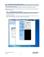
Page 33: ...omatically until the scanner is updated via the website Additionally the access with the web browser allows the set up directly of the working IP address the Port and the Subnet mask 10 1 Changing the...

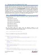
Page 34: ...d EthernetScanner dll These functions are EthernetScanner_Connect EthernetScanner_Disconnect EthernetScanner_GetConnectStatus EthernetScanner_GetScanRawData EthernetScanner_GetInfo EthernetScanner_Wri...

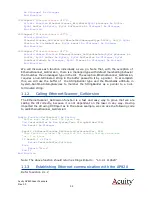
Page 35: ...ersion requires a null terminated string in the buffer passed to it by a pointer To accomplish this we will use the buffer of the StringBuilder type and the MarshalAs attribute in System Runtime Inter...

Page 36: ...string containing the TCP Port default value is 3000 Timeout is an unsigned integer containing the number of milliseconds to wait for a response If successful this function returns a pointer to an ob...

Page 37: ...shalAs UnmanagedType ByValTStr sizeconst 128 Public FirmwareVersion As String Public BeginningOfMeasuringRange As UInteger Public MeasuringRange As UInteger Public ScanRangeBeginning As UInteger Publi...

Page 38: ...20 by calling EthernetScanner_GetScanRawData The function is or the following form Private Function EthernetScanner_GetScanRawData ByVal pScanner As IntPtr ByVal Buffer As Byte ByVal BufferSize As UIn...

Page 39: ...pixel scans at the rate of approximately 200 Hz On the other hand if he she wishes to resolve the horizontal field of view into 580 parts and the measured target is assumed not to change during the ti...

Page 40: ...x 62 This image counter increments by one each time a new scan is obtained and resets to zero every 254 scans This counter can be used to identify odd numbered vs even numbered scans We would use the...

Page 41: ...I 5 3 And H7F 7 Intensity IArray I 2 1 CUInt Buffer 66 I 5 4 Next Else something went wrong Return False End If Else Return False End If Return Result End Function At this point both the X and Z arra...

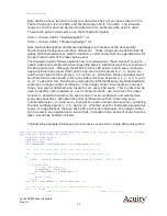
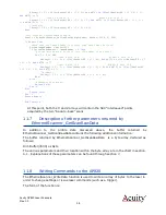
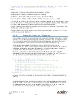
Page 42: ...y other register related operation should be straight forward by analogy For example let s consider commands to turn on and to turn off the laser programmatically We see in the Register of Functions t...

Page 43: ...gs demonstrates how to limit the range Z of the AP820 Limiting the range Z of the laser may be very helpful in removing foreground or background objects from the measurement process in order to only a...

Page 44: ...ing is a table of settings commands and associated Register Addresses which can be accessed via the EthernetScanner_WriteData function Refer to section 9 for descriptions of the purpose of each of the...

Reviews: