Installation
EN-US · 30.30.01.02237 · 00 · 04/20
83 / 94
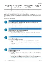
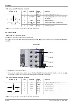
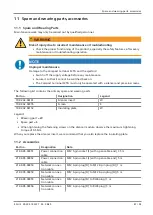
Pin Assignments, L-coded M12 Connector for Voltage Supply
M12-L connector
PIN
Symbol
Wire color
1)
Function
1
2
3
4
5
1
U
s
Brown
Supply voltage for sensor
2
GND
A
White
Actuator ground
3
GND
s
Blue
Sensor ground
4
U
A
Black
Supply voltage for actuator
5
FE
Gray
Functional ground (earth)
1)
When using a Schmalz connection cable (see accessories)
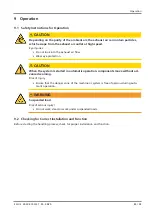
Pin Assignments, D-coded M12 Socket for Industrial Ethernet
M12-D socket
PIN
Symbol
2
1
4
3
1
TX+
2
RX+
3
TX-
4
RX-
Thread
FE
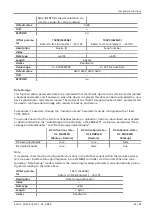
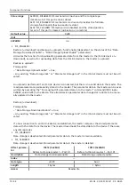
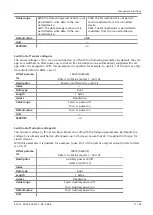
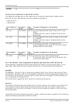
8.4.3 IOL Master Module
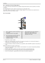
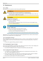
Mounting the Connection Cable
Mount the connection cable to the IOL master module.
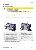
The figure shown here is an example. Depending on the design of the terminal, one or two IOL master
modules are installed.
IOL Master Module
Port X1
Port X2
Port X3
Port X4
ü
Prepare the connection cable (maximum length = 20 m).
4
Connect the connection cable to one of the four 5-pin M12 sockets (Port X1 to X4) on the IOL master
module and tighten the union nut with the max. tightening torque (hand-tight).

