Component Functions
76 / 94
EN-US · 30.30.01.02237 · 00 · 04/20
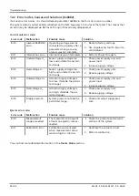
If a length is specified in the CIP object, write access takes place. If length 0 is specified, read access takes
place. In case of an error, an error code and an extended error code are returned. The error code can be
found in the system information. The extended error code describes the error in accordance with the IO-
Link interface specification.
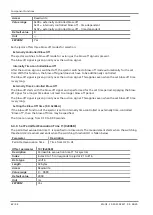
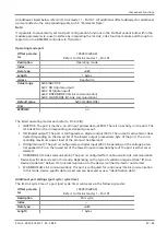
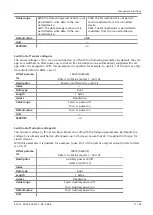
The CIP object must be provided with the following parameters:
Message type
CIP generic
Service type
Custom
Service code
See above table for master and port
Instance
Index
Class/object
0x10B
Attribute
Subindex
Source length
0 for read access; parameter length for write
access
6.6 DI Module Functions
Status of the Input Ports via Process Data
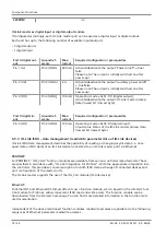
The status of each input (valid signal on/valid signal off) can be read via process data or parameter data.
Each DI module has 8 digital inputs: 2 inputs per port.
A maximum of 6 DI modules can be installed on one terminal. Thus, up to 48 digital inputs are possible on
the compact terminal.
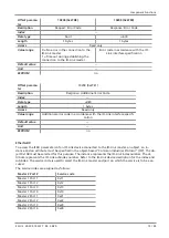
Status via Input Process Data:
EtherNet/IP + EtherCAT:
An input process data byte is fixed for each DI module in both variants.
--> See 5.2 “Process Data”.
PROFINET:
By selecting appropriate modules/submodules (predefined in the device description file), the DI modules
can be specifically defined in the process data that is actually present.
--> See 5.2 “Process Data”.
For a detailed description of the corresponding process data --> see 5.2 “Process Data”.
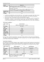
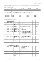
Status via Parameter Data:
Digital input status
This parameter is used to determine the current status of each input.
Parameter
34 (0x0022)
Description
Digital input status
Subindex
Index 0..5 corresponds to DI module #1…#6
Data type
Subindex
uint8
Length
8 bytes
Access
Read only
Value range
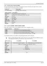
Bit 0 = DI module status; Port X1, Pin (2)
Bit 1 = DI module status; Port X1, Pin (4)
Bit 2 = DI module status; Port X2, Pin (2)
Bit 3 = DI module status; Port X2, Pin (4)
Bit 4 = DI module status; Port X3, Pin (2)

