

IG-500E
IG Device Integration Manual
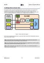
4. Aiding Sensors flow chart
The diagram below shows how the aiding sensors of the remote IG-Device are sampled and
realigned into the IG-500E coordinate frame. IG-Device remote magnetometer output is
temperature compensated, but not calibrated for hard/soft iron effects. In addition, an alignment
may be required to get IG-Device coordinate frame consistent with the IG-500E one.
As you can see, alignment parameters, as well as the Hard and Soft Iron compensation data are
stored into IG-500E memory.
Note 1:
If the calibration and orientation offset parameters are required to be stored in the
remote IG-Device, please contact factory for more information.
Note 2:
For best results, please make sure that the IG-Device magnetometers soft iron matrix is
set to identity and that the hard iron offset is set to (0,0,0).
Note 3:
GPS and barometer give direct data to the IG-500E, so no calibration parameter is
stored in one or another device.
SBG Systems
7/11
IG500EIIDG.3
Figure 1: Sensor data flow diagram
IG-500E
Mx
My
Mz
Orientation
Offset
Hard / Soft
Iron
Comp.
Remote
IG-Device
Magnetometer
K
al
m
an
F
ilt
er
Pos
Vel
P
Internal
Mag.
Heading
Source
GPS
Barometer


