Savant Power System Deployment Guide - Sol-Ark
Copyright 2022 Savant Systems, Inc
009-2222-01 | 121222
- 17 -
6.2. Configuration
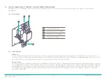
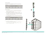
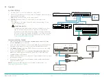
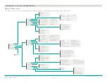
Battery Addressing
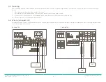
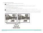
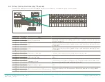
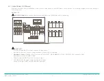
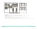
The BMS and all Battery Modules must have their address configured according to its position within the battery stack. The diagram below shows
an example of four modules in a stack, but the maximum height of a stack is 8 modules The table next to the diagram shows the dial code switch
position per position within the stack.
For information on multiple battery stacks, see the HomeGrid Manual.
Addr SET
ON
1 2 3 4 5 6
3
1
4
2
BMS
Base
Address
1
2
3
4
BMS
ON
OFF
OFF
OFF
1
ON
OFF
OFF
OFF
2
OFF
ON
OFF
OFF
3
ON
ON
OFF
OFF
4
OFF
OFF
ON
OFF
5
ON
OFF
ON
OFF
6
OFF
ON
ON
OFF
7
ON
ON
ON
OFF
8
OFF
OFF
OFF
ON
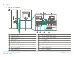
EMS
LAN
Link-B
Link-A
CAN
RS485
COM
RS232
Dry Contact
Invert COMM
Half Current
Invert SET
Addr SET
Imped SET
ON
1 2 3 4 5 6
ON
1 2 3 4 5 6
ON
1 2 3 4 5 6
1
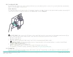
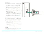
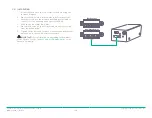
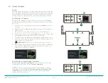
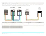
Wire Battery Monitoring System
1.
Install included bus bars onto the Battery Monitoring System
Battery terminals.
2. Connect the battery power cables to the bus bar to the Sol-
Ark inverter.
3. Connect the communication cable to the ports detailed in
section 5.8 Communication
.

